A polyhedron-based array spray cooling surface

A heat dissipation surface and array technology, applied in the direction of cooling/ventilation/heating transformation, electrical components, electrical equipment structural parts, etc., can solve the problems of poor liquid drainage on the spray surface, limited heat exchange area, limited heat source area, etc. Achieve the effects of improving heat transfer effect, increasing heat transfer area, and simple surface processing

Active Publication Date: 2020-08-11
NANJING UNIV OF SCI & TECH
View PDF6 Cites 0 Cited by
  • Summary
  • Abstract
  • Description
  • Claims
  • Application Information

AI Technical Summary

Problems solved by technology

[0003] Many studies have proved that spray cooling has the advantages of higher heat transfer coefficient, lower flow rate, and uniform cooling, and is an effective way to solve the heat dissipation problem of such electronic equipment, but the existing spray cooling technology has the following disadvantages: (1 ) At present, the spray cooling surface mainly adopts a smooth flat surface or a flat surface with a microstructure. The processing of a smooth flat surface is relatively simple, but the heat transfer area is limited. The microstructure surface can effectively increase the heat transfer area and improve the spray cooling performance, but the processing is more complicated. ; (2) The liquid drainage effect on the surface of the flat plate and the microstructure spray is poor, and it is easy to cause some droplets to not completely evaporate and remain on the surface of the heat source to form a water film, which reduces the heat transfer effect; (3) The larger the area of ​​the plate structure, the easier it is to produce a water film Insufficient heat dissipation and limited heat source area available

Method used


Image

  • A polyhedron-based array spray cooling surface
  • A polyhedron-based array spray cooling surface
  • A polyhedron-based array spray cooling surface

Examples


Embodiment Construction

[0018] The solutions of the present invention will be further described below in conjunction with the accompanying drawings and specific embodiments.

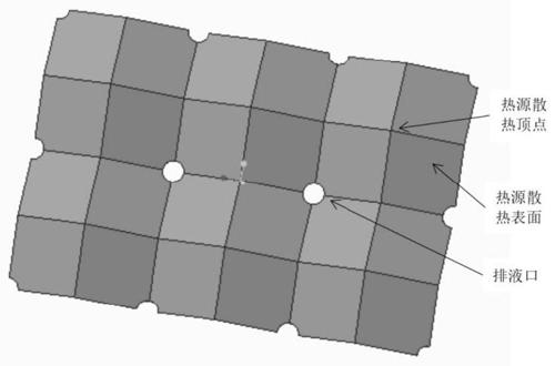
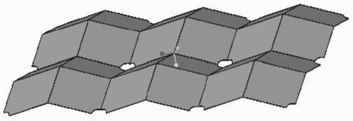
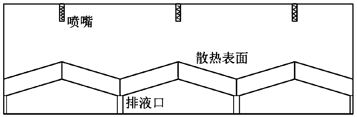
[0019] The present invention is based on a polyhedron array spray heat dissipation surface, including several heat dissipation units, the heat dissipation units are three-dimensional structural surfaces spliced ​​by multiple planes, arranged in an array to form a complete heat dissipation surface; nozzles are arranged above the heat dissipation surface , a liquid discharge pipe is arranged below, and a liquid discharge port is provided at the depression of the cooling surface, wherein the liquid discharge port is connected with the liquid discharge pipe. In the present invention, the heat dissipation surface is made into a three-dimensional structural surface, and then the heat dissipation surface of required size is formed through array combination. During the heat dissipation process, the liquid droplets are sprayed to the he...


PUM


Abstract

The invention discloses an polyhedron-based array spray cooling surface, comprising a plurality of heat dissipation units, wherein the heat dissipation units are three-dimensional structural surfacesformed by splicing a plurality of planes and are arranged according to an array to form a complete heat dissipation surface; A nozzle is arranged above the heat dissipation surface, a liquid dischargepipe is arranged below the heat dissipation surface, and a liquid discharge port is arranged at the concave part of the heat dissipation surface, wherein the liquid discharge port is connected with the liquid discharge pipe, and unvaporized liquid on the heat dissipation surface is discharged through the liquid discharge port and the liquid discharge pipe. Compared with a smooth plate surface, the invention increases the heat exchange area, improves the heat exchange effect, simplifies the surface processing of the micro-structure plate, saves the cost, restrains the formation of water on thespray cooling surface, helps to reduce the thickness of the liquid film, and improves the heat exchange coefficient of the spray cooling surface.

Description

technical field [0001] The invention relates to spray cooling technology, in particular to a polyhedron-based array spray cooling surface. Background technique [0002] A large amount of heat is generated during the use of electronic products. If this part of the heat cannot be dissipated in time, the temperature of electronic devices will rise sharply, which will greatly reduce the stability and life of electronic products, and even damage them. With the miniaturization and integration of semiconductor electronic products, the local heat flux density of electrical devices is getting higher and higher, and the problem of thermal safety of electronic products has become increasingly prominent. Therefore, it is particularly important to solve the heat dissipation problem of high-power, high-heat-flux electronic equipment. [0003] Many studies have proved that spray cooling has the advantages of higher heat transfer coefficient, lower flow rate, and uniform cooling, and is an...

Claims


Application Information

Patent Timeline
Patent Type & Authority Patents(China)
IPC IPC(8): H05K7/20
CPCH05K7/20345
Inventor 胡定华阮家双李强
Owner NANJING UNIV OF SCI & TECH
Why Eureka
Try Eureka