A same-layer drainage device and construction method thereof

A construction method and a same-layer drainage technology are applied in the field of drainage devices and vertical pipes and drainage devices on the same layer, which can solve the problems of failure of opening and closing of the water outlet, difficult connection of the drainage transverse branch pipe, and no socket and socket interface at the water outlet, so as to achieve drainage. The mute effect is remarkable, the water accumulation in the box is suppressed, and the effect of water evaporation is favorable.

Active Publication Date: 2017-03-15
JIANGSU HUAJIAN CONSTR
View PDF9 Cites 0 Cited by
  • Summary
  • Abstract
  • Description
  • Claims
  • Application Information

AI Technical Summary

Problems solved by technology

However, the drainage floor drain on the same floor is in the shape of a cylinder, and its height is large. After the installation, the thickness of the leveling layer must be increased, which will affect the thickness of the backfill; the cylinder needs to be raised and fixed during installation, and a margin must be left at the lower end. It is convenient to open and close the water outlet, and this gap needs to be reserved during leveling construction, which greatly increases the difficulty of construction; the water outlet has no socket interface, and it is not easy to connect with the horizontal branch pipe of the drainage; when the water flow velocity is high, the sewage is easy to A vortex is generated in the cylindrical cylinder, and then a centrifugal force is generated to shake the cylinder; the opening and closing of the water outlet is realized by the mutual attraction of the permanent magnet 1 and the permanent magnet 2, which may be interfered by external factors. It is easy to cause the opening and closing function of the water outlet to fail

Method used


Image

  • A same-layer drainage device and construction method thereof
  • A same-layer drainage device and construction method thereof
  • A same-layer drainage device and construction method thereof

Examples


Embodiment 1

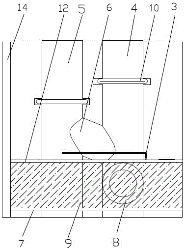
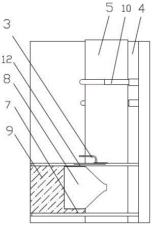
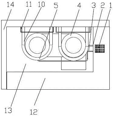
[0031] The present embodiment is the same layer drainage device of toilet, as Figure 1 to Figure 7 As shown, it includes a cast iron ventilation standpipe 5, a drainage standpipe 4 inserted through the floor slab, and a floor drain 1 placed on the upper surface of the floor slab.

[0032] The floor slab is composed of a floor slab 12, a descending slab 7, and a filler 9 filled between the floor slab 12 and the descending slab 7. The filler can be selected from lightweight materials such as ceramsite, fly ash, vermiculite, lightweight concrete, and their mixtures. . The ventilation riser 5 communicates with the drainage riser 4 through an inclined tee 6 , and the high end of the inclination tee 6 is connected to the ventilation riser 5 . The drainage standpipe 4 is communicated with the drainpipe on the same floor through the vertical tee 8 between the floor board 12 and the descending plate 7, and then communicated with the downpipe of the toilet and washbasin through the dr...


PUM


Abstract

The invention relates to a same-layer drainage device and a construction method thereof, and belongs to the technical field of drainage facilities. The same-layer drainage device comprises a ventilating vertical pipe, a drainage vertical pipe and a floor drain which are located on a floor. The ventilating drainage pipe is communicated with the drainage vertical pipe through an inclined three-way joint. The drainage vertical pipe is communicated with a same-layer drainage pipe through a vertical three-way joint. A drainage opening and a ventilating opening are formed in the middle, in the height direction, of the drainage end of the floor drain. A middle partition plate is arranged in the middle of a box body. A water sealing plate is arranged between the drainage end and the middle partition plate. A slope facing the drainage end is arranged at the bottom of the box body. The drainage opening is communicated with the drainage vertical pipe through a horizontal connecting pipe. The ventilating opening is communicated with the ventilating vertical pipe through a climbing connecting pipe. The defect that when a traditional floor drain is installed, a drainage pipe is located on the lower layer and interferes with construction of a ceiling on the lower layer is overcome, the edge of an upper opening of the floor drain is flush with or slightly lower than the floor, the drainage requirement is met, a waterproof layer of the floor is not damaged, the drainage silencing effect is remarkable, and bacterium breeding and odor are avoided.

Description

technical field [0001] The invention relates to a drainage device, in particular to a vertical pipe same-floor drainage device for toilets and the like, and belongs to the technical field of drainage facilities. Background technique [0002] According to the applicant's knowledge, the drainage pipes of the traditional floor drain are all exposed to the bottom of the floor, thus affecting the construction of the lower ceiling. The Chinese invention patent No. 99116082.7 authorized in the last century and the Chinese invention patent No. 201410057667.5 authorized not long ago all have the above structural characteristics. In order to solve this problem, devices such as floor drains for drainage on the same floor have appeared one after another. Although this type of device has the effect of improving the suspended ceiling of the lower floor, other original performances are deteriorated to varying degrees. For example, the Chinese patent application number 200610012494.0 discl...

Claims


Application Information

Patent Timeline
Patent Type & Authority Patents(China)
IPC IPC(8): E03F5/04
CPCY02A30/60
Inventor 缪昌华吴碧桥钱雪松郭国庆施高成
Owner JIANGSU HUAJIAN CONSTR
Why Eureka
Try Eureka