
Energy-saving controllable low-temperature freezing point pulverizing device

A crushing device and energy-saving technology, which is applied in the field of energy-saving and controllable low-temperature freezing point crushing devices, can solve problems such as unreasonable arrangement of hammers and knives, volatilization and loss of effective components, and unsatisfactory classification effects, so as to avoid repeated crushing, dust and airflow Smooth flow and reduced loss of effect

Pending Publication Date: 2019-01-29
李国清
View PDF0 Cites 3 Cited by
  • Summary
  • Abstract
  • Description
  • Claims
  • Application Information

AI Technical Summary

Problems solved by technology

Although there are many ultra-fine pulverizing devices at present, many of the ultra-fine pulverizing devices currently in use do not have a cooling or freezing system. During the continuous pulverizing process, a large amount of heat will be generated due to mutual friction and collision with the pulverizing hammer. If the heat is not taken away in time, various problems such as coking, clogging, volatilization and loss of effective components will occur for those substances that need to be pulverized that contain oils, starches, sugars, and aromatic substances; at the same time, some Although the device adopts the integrated design of crushing and grading, the grading effect is not ideal, and the arrangement of hammers and knives on the crushing disc is not reasonable enough

Method used


Image

  • Energy-saving controllable low-temperature freezing point pulverizing device
  • Energy-saving controllable low-temperature freezing point pulverizing device
  • Energy-saving controllable low-temperature freezing point pulverizing device

Examples


Embodiment Construction

[0025] The present invention will be further described below in conjunction with drawings and embodiments.

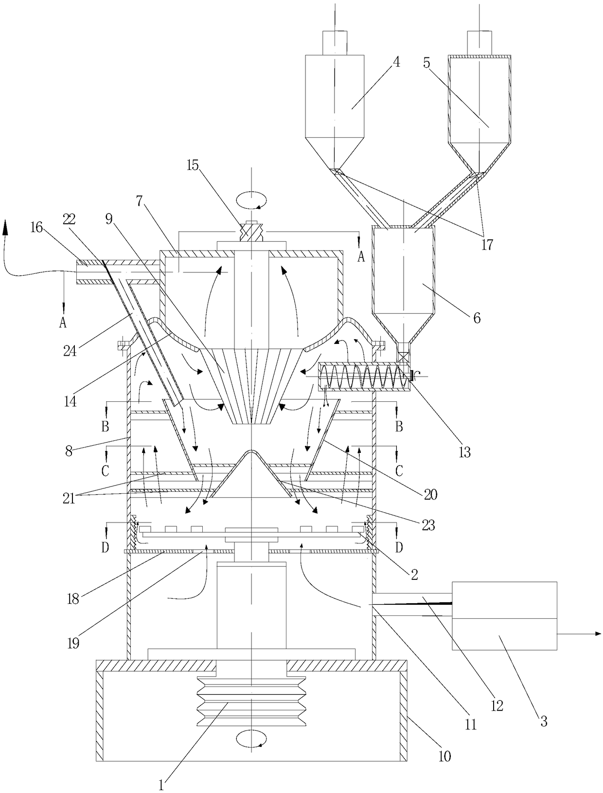
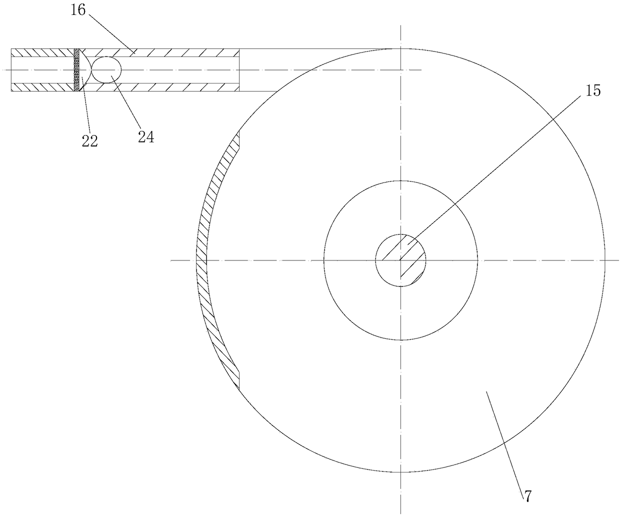
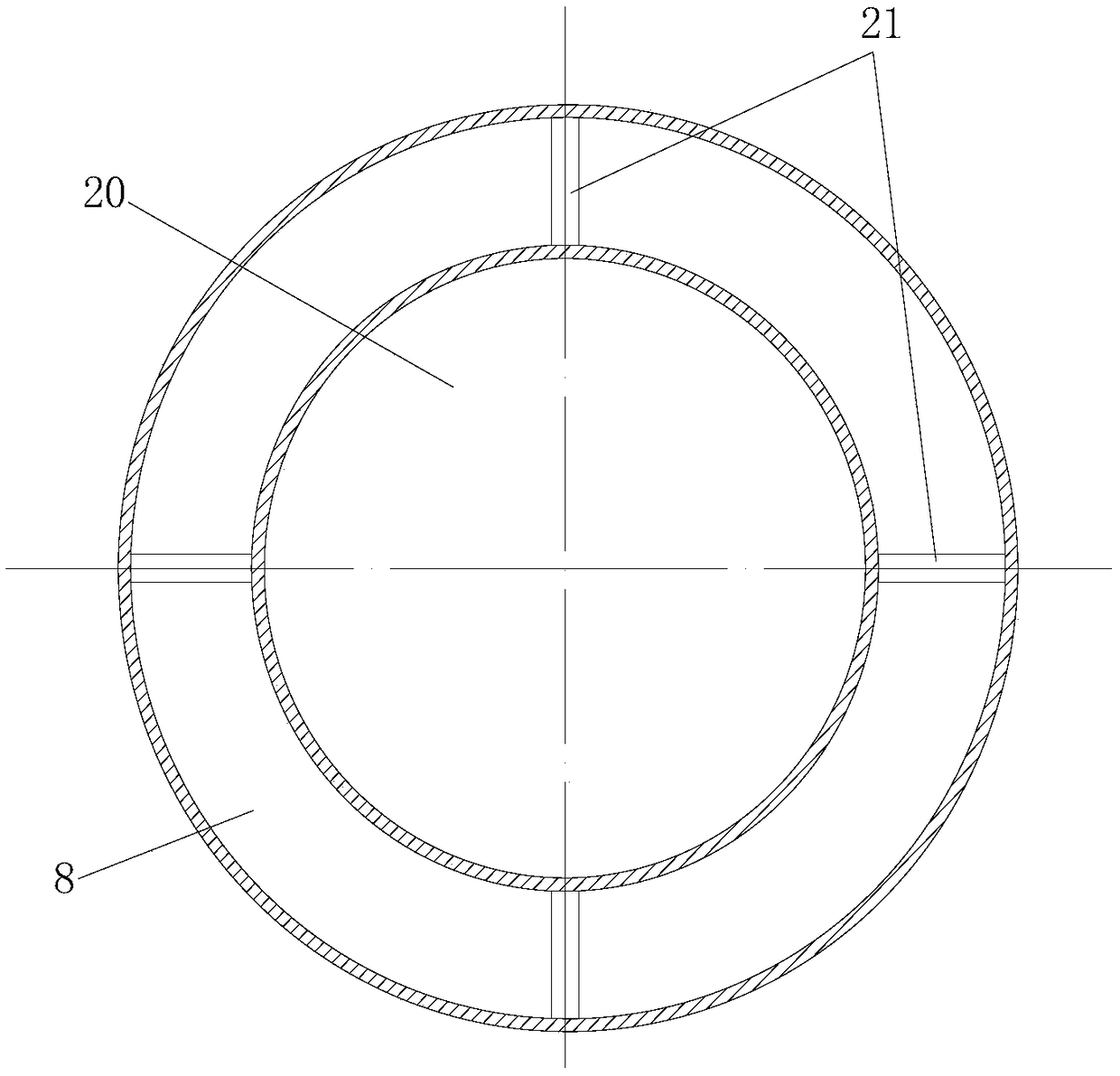
[0026] Such as figure 1 and figure 2 The shown energy-saving controllable low-temperature freezing point crushing device includes a crushing motor, a crushing mechanism, a heat pump, a material bin, a dry ice bin, a mixing bin, a classifying bin, a crushing bin and a classifying turbine. The crushing motor is installed on the side of the crushing bin through a base The lower end, the crushing mechanism is installed in the crushing bin, and the crushing mechanism is connected to the crushing motor; the lower end of the side wall of the crushing bin is provided with a cold air inlet communicating with the inner cavity of the crushing bin, and the cold air inlet is located at Below the crushing mechanism, the cold air inlet is connected to the cold air outlet of the heat pump through the cold air pipe; the material bin and the dry ice bin are both connected to the feedin...


PUM

PropertyMeasurementUnit
Angleaaaaaaaaaa

Abstract

The invention discloses an energy-saving controllable low-temperature freezing point pulverizing device. The energy-saving controllable low-temperature freezing point pulverizing device comprises a pulverizing motor, a pulverizing mechanism, a heat pump, a material bin, a dry ice bin, a mixing bin, a classifying bin, a pulverizing bin and a classifying turbine; the pulverizing motor is installed at the lower end of the pulverizing bin through a base; the pulverizing mechanism is installed in the pulverizing bin through the pulverizing motor; the lower end of the pulverizing bin is provided with a cold air inlet communicating with an inner cavity of the pulverizing bin; the cold air inlet is located in the lower portion of the pulverizing mechanism; the cold air inlet is connected with an cold air outlet of the heat pump through a cold air pipe; the material bin and the dry ice bin are connected with the feeding end of the mixing bin; the discharging end of the mixing bin is connected with the pulverizing bin through a screw feeder; the screw feeder communicates with the inner cavity of the pulverizing bin; the classifying bin is installed at the upper end of the pulverizing bin through a convex cover; the classifying bin is provided with a classifying motor; and the classifying turbine is connected with the classifying motor. Materials can be prevented from being pulverized ata high temperature, the quality of the pulverized materials is ensured, and cooling capacity can be fully utilized.

Description

technical field [0001] The invention relates to crushing equipment technology, in particular to an energy-saving and controllable low-temperature freezing point crushing device. Background technique [0002] The crushing device is widely used in the pharmaceutical industry, especially in the crushing and processing industry of Chinese herbal medicines with high temperature requirements. At present, the commonly used crushing devices include hammer type, ball mill type, air flow type and other crushing devices. Although there are many ultra-fine pulverizing devices at present, many of the ultra-fine pulverizing devices currently in use do not have a cooling or freezing system. During the continuous pulverizing process, a large amount of heat will be generated due to mutual friction and collision with the pulverizing hammer. If the heat is not taken away in time, various problems such as coking, clogging, volatilization and loss of effective components will occur for those su...

Claims


Application Information

Patent Timeline
IPC IPC(8): B02C13/14B02C13/28B02C13/282B02C13/286B02C13/26B02C19/18B02C23/24
CPCB02C13/14B02C13/26B02C13/28B02C13/282B02C13/286B02C19/186B02C23/24B02C2013/28609
Inventor 李宝曦黄燕娣李国清谢文颖
Owner 李国清
Learn More