
Dry ice cleaning nozzle with function of stabilizing flow direction of dry ice

A technology of dry ice cleaning and dry ice, which is applied in the direction of spraying devices, liquid spraying devices, cleaning methods and appliances, etc., can solve the problems of narrow range, small spraying angle, and small cleaning area, and achieve wide spraying range and large spraying angle. Effect

Pending Publication Date: 2019-01-29
XIAMEN UNIV OF TECH
View PDF6 Cites 1 Cited by
  • Summary
  • Abstract
  • Description
  • Claims
  • Application Information

AI Technical Summary

Problems solved by technology

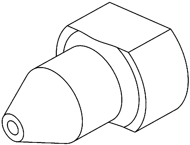
[0004] In the above-mentioned prior art scheme, the compressed air in the previous proposal is only discharged through one cavity (i.e., the air flow channel), and the nozzle body and the opening of the outer cover in the previous proposal are located on the same horizontal plane, and the compressed air ejected has a large impact on the The degree of encapsulation of the sprayed dry ice particles is not strong, and it does not have a strong steady flow effect on the sprayed dry ice, and the flow direction of the dry ice after spraying is not stable enough
[0005] In addition, the main body of the nozzle is cylindrical, so the spray angle of the spray outlet of such a spray head is small, the coverage area after spraying is narrow, and the cleaning area is small

Method used


Image

  • Dry ice cleaning nozzle with function of stabilizing flow direction of dry ice
  • Dry ice cleaning nozzle with function of stabilizing flow direction of dry ice
  • Dry ice cleaning nozzle with function of stabilizing flow direction of dry ice

Examples


Embodiment Construction

[0031] In order to make the object of the present invention, technical scheme and advantage clearer, below in conjunction with appendix Figure 2-6 The present invention will be described in further detail through the following examples and embodiments. It should be understood that the specific implementation described here is only used to explain the present invention, and is not intended to limit the present invention.

[0032] In a specific embodiment, the specific implementation mode of the present invention is as follows:

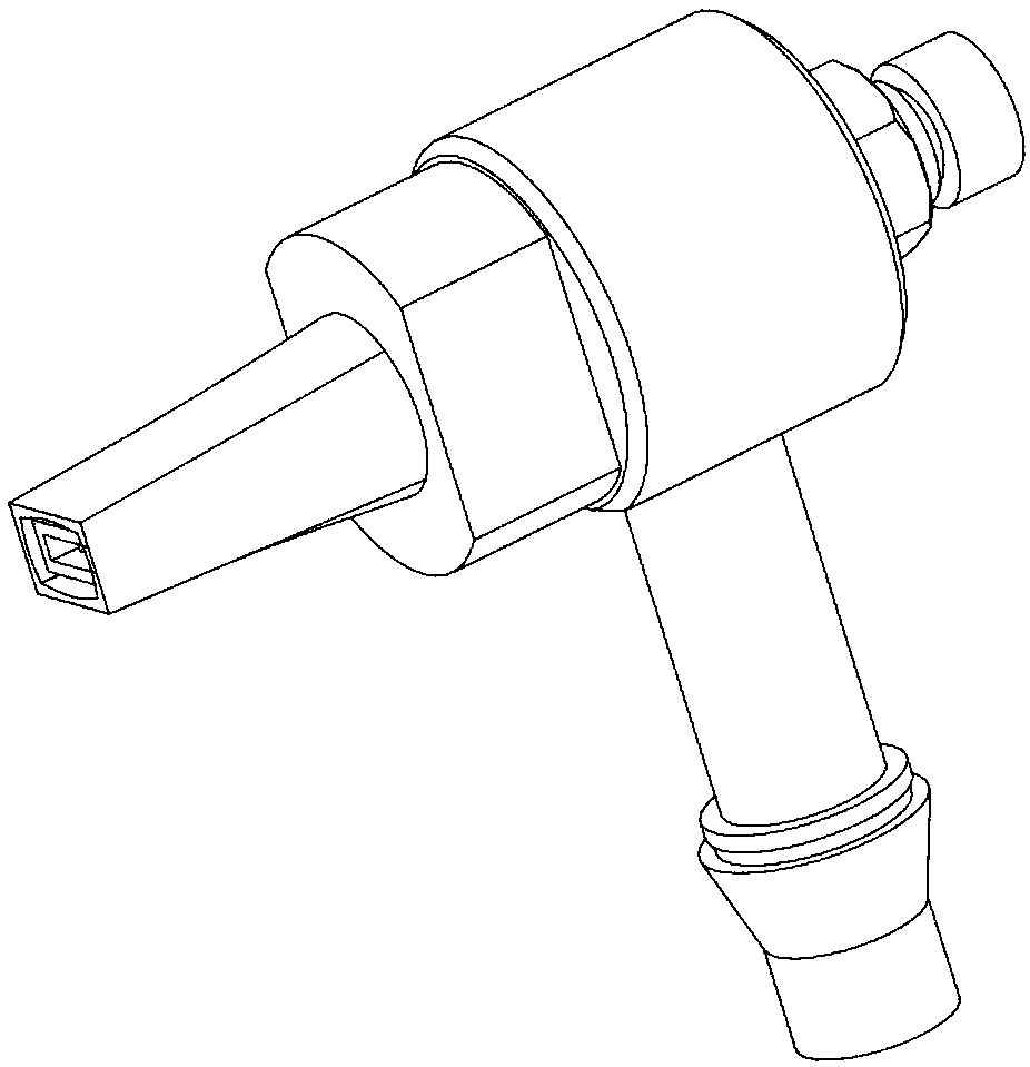
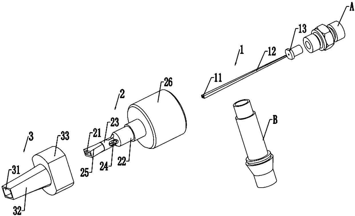
[0033] Such as figure 2 The shown dry ice cleaning nozzle with the function of stabilizing the flow direction of dry ice mainly includes a dry ice nozzle 1 , a compressed air nozzle 2 and a nozzle cover 3 . another example Image 6 As shown, a first gap W is formed between the dry ice nozzle 1 and the compressed air nozzle 2 for compressed gas to be ejected, and a first gap W is formed between the compressed air nozzle 2 and the nozzle cover 3 . Tw...


PUM


Abstract

Disclosed is a dry ice cleaning nozzle with the function of stabilizing the flow direction of dry ice. The dry ice cleaning nozzle comprises a dry ice spray pipe, a compressed air spray pipe and a nozzle cover, wherein the dry ice spray pipe is provided with a first air inlet and a first spray port, the compressed air spray pipe is provided with a second air inlet and a second spray port, and thenozzle cover is provided with a third spray port. The dry ice spray pipe, the compressed air spray pipe and the nozzle cover are sequentially arranged from inside to outside with the same central axisin a sleeving mode. The first spray port is positioned in the second spray port, and the second spray port is positioned in the third spray port. A first cavity and second cavity with gaps for ejecting compressed air out are formed among the dry ice spray pipe, the compressed air spray pipe and the nozzle cover. The compressed air ejected at a high speed through the first cavity drives the dry ice in the middle to increase the kinetic energy of the dry ice and play a role in flow stabilizing; and the compressed air of the second cavity wraps the dry ice at the outermost periphery, so that dryice ejection is more stable.

Description

technical field [0001] The invention relates to the field of dry ice cleaning, in particular to a dry ice cleaning nozzle with the function of stabilizing the flow direction of dry ice. Background technique [0002] Dry ice cleaning, also known as cold spray, uses compressed air as the power and carrier, and dry ice particles as the accelerated particles, which are sprayed onto the surface of the object to be cleaned through a special jet cleaning machine, and will not damage the surface of the object to be cleaned, especially the metal surface. It will not cause any harm and will not affect the finish of the metal surface. In order to achieve a good dry ice blasting effect, the design of the dry ice nozzle is very important. [0003] Such as figure 1 Shown, in existing patent literature (patent application publication number, CN107377531A), it discloses a kind of dry ice snowflake cleaning nozzle device, comprises nozzle main body, the outer cover that is connected with n...

Claims


Application Information

Patent Timeline
IPC IPC(8): B05B7/14B08B7/00
CPCB05B7/1486B08B7/00
Inventor 陈水宣梁彬彬李磊叶少伟卓仕耀
Owner XIAMEN UNIV OF TECH
Learn More