Scraping plate error correcting tool

An error correction and scraper technology, applied in the field of fixtures, can solve problems such as low efficiency and complicated operation, and achieve the effect of saving error adjustment steps and improving work efficiency

Pending Publication Date: 2019-01-29
CHINA AVIATION OIL CO LTD ZHEJIANG BRANCH
View PDF0 Cites 0 Cited by
  • Summary
  • Abstract
  • Description
  • Claims
  • Application Information

AI Technical Summary

Problems solved by technology

The graphite scraper needs to be continuously disassembled and measured during the adjustment process, which is complicated to operate and low in efficiency

Method used


Image

  • Scraping plate error correcting tool
  • Scraping plate error correcting tool
  • Scraping plate error correcting tool

Examples


Embodiment 1

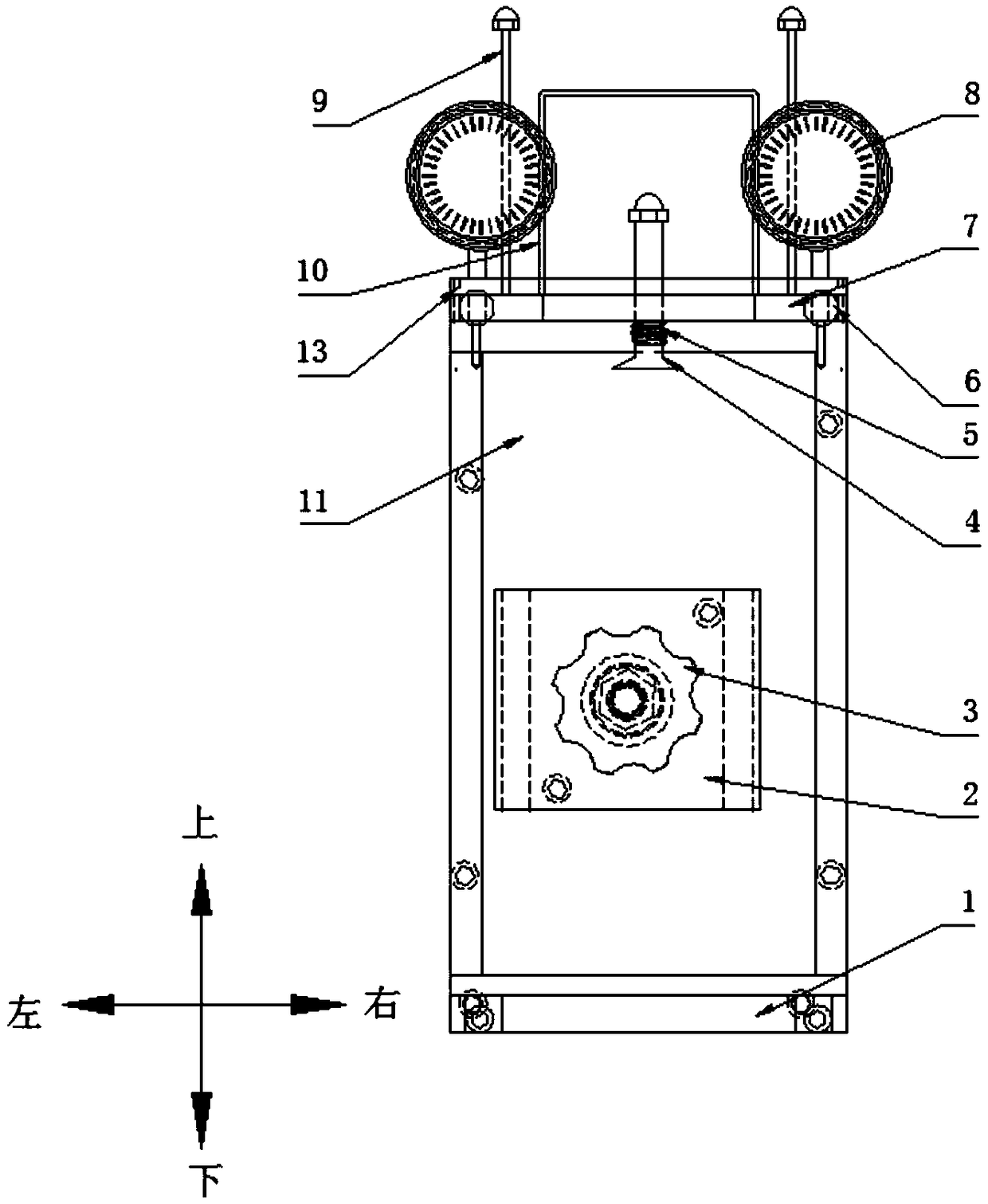
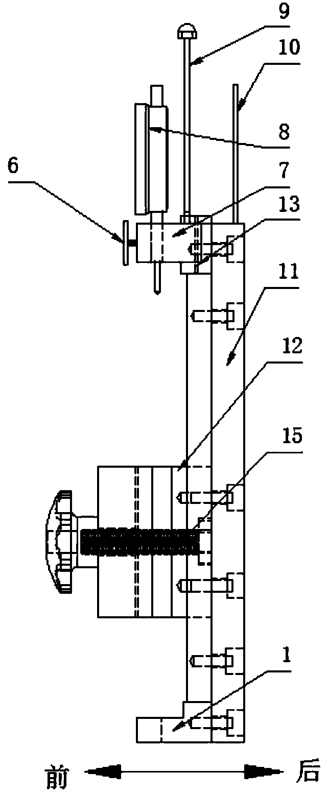
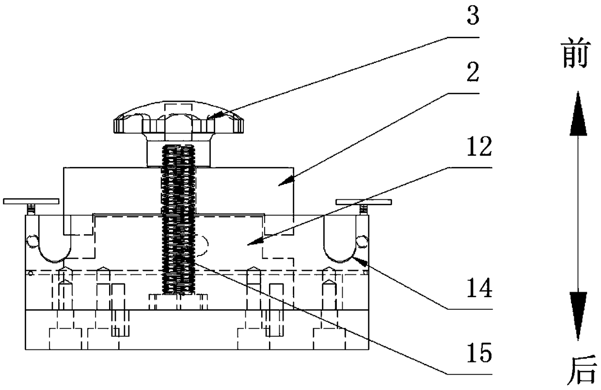
[0045] like Figure 1-Figure 8 As shown, a scraper error correction tool includes a scraper positioning assembly, a base 11, two dial indicator fixing blocks 7 and two dial indicators 8, and the scraper positioning assembly is in phase with the base 11. The scraper positioning assembly has two grooves 14 for accommodating an outer micrometer anvil or a micrometer screw. The two dial indicator fixing blocks 7 are rotatably connected to the base 11, and the two The dial indicator 8 and the two dial indicator fixing blocks 7 are arranged in a one-to-one correspondence and are penetrated in the dial indicator fixing block 7, and the groove 14 is one with the dial indicator 8. A corresponding arrangement, the dial indicator 8 is in contact with or separated from the scraper with the change of the relative position of the dial indicator fixing block 7 and the base 11 .

[0046] Specifically, as Figure 1-Figure 8 As shown, the dial indicator fixing block 7 has a through hole, and ...

Embodiment 2

[0069] On the basis of the first embodiment, the rotational connection between the dial gauge fixing block 7 and the base 11 is replaced by a sliding connection.

[0070] like Figure 9 and Figure 10 As shown, it includes two locking and positioning rods 17, and the base 11 is provided with two horizontal slide grooves, and the dial gauge fixing block 7 is embedded in the slide grooves and slides relative to the slide grooves. , the side wall of the chute has two locking holes perpendicular to the chute, the locking holes are set in one-to-one correspondence with the dial gauge fixing block 7, and the locking positioning rod 17 and the The locking holes are connected one by one and abut against the dial gauge fixing block 7 .

[0071] like Figure 9 As shown, in the process of adjusting the scraper, unscrew the left and right dial indicator lock nuts 6, adjust the position of the dial indicator 8 up and down, so that the contact of the dial indicator 8 is in contact with the...


PUM


Abstract

The invention relates to a scraping plate error correcting tool. The scraping plate error correcting tool comprises a scraping plate locating assembly, a base, at least one dial indicator fixing blockand at least one dial indicator; the scraping positioning assembly is connected to the base, and the scraping plate positioning assembly is provided with at least one groove which are used for containing outer diameter micrometer measuring anvils or micrometer screw rods; the dial indicator fixing blocks are in rotating connection with the base and are in sliding connection with the base, the dial indicators and the dial indicator fixing blocks are arranged in a one-to-one correspondence mode, and the dial indicators are arranged in the dial indicator fixing blocks in a penetrating mode; andthe grooves and the dial indicators are arranged in a one-to-one correspondence mode, and the dial indicators are in contact with or separated from a scraping plate along with the changes of the relative positions of the dial indicator fixing blocks and the base. According to the scraping plate error correcting tool, repeated loading and unloading in the process of adjusting the scraping plate canbe avoided, and the distance between the two end surfaces of the graphite scraping plate is accurately measured and adjusted. The scraping plate error correcting tool has the advantages that the error correcting efficiency of the scraping plate can be improved.

Description

technical field [0001] The invention relates to the field of tooling fixtures, in particular to a scraper error correction tooling. Background technique [0002] Graphite scraper flowmeter is a type of positive displacement flowmeter. When the measured fluid flows into the flowmeter from the inlet of the flowmeter, a pressure difference is generated between the inlet and outlet of the flowmeter, which pushes the scraper and the rotor to rotate. . The rotor discharges a certain amount of fluid every time it rotates, and the instantaneous flow and cumulative flow are obtained by calculating the number of rotations of the rotor. [0003] The graphite scraper rotor rotates in the cavity of the flowmeter, and there is a small gap between the end face of the graphite scraper and the inner wall of the cavity. If the gap is too small, the graphite scraper will scrape against the inner wall of the cavity. If the gap is too large, the counter cannot count normally when the scraper r...

Claims


Application Information

Patent Timeline
Patent Type & Authority Applications(China)
IPC IPC(8): B25B11/00G01B5/14
CPCB25B11/00G01B5/14
Inventor 袁志民
Owner CHINA AVIATION OIL CO LTD ZHEJIANG BRANCH
Why Eureka
Try Eureka