Method for measuring transmission loss of asymmetric pipeline silencer

A transmission loss and measurement method technology, applied in the field of measurement, can solve the problems of narrow measurement frequency range, etc., and achieve the effect of easy operation, strong flexibility and wide application range

Inactive Publication Date: 2013-07-24
HARBIN ENG UNIV
View PDF5 Cites 14 Cited by
  • Summary
  • Abstract
  • Description
  • Claims
  • Application Information

AI Technical Summary

Problems solved by technology

When the size of the muffler increases or the frequency to be measured is high, all the above methods have limitations, and the effective measurement frequency range is narrow

Method used


Image

  • Method for measuring transmission loss of asymmetric pipeline silencer
  • Method for measuring transmission loss of asymmetric pipeline silencer
  • Method for measuring transmission loss of asymmetric pipeline silencer

Examples


Embodiment Construction

[0021] The present invention is described in more detail below in conjunction with accompanying drawing example:

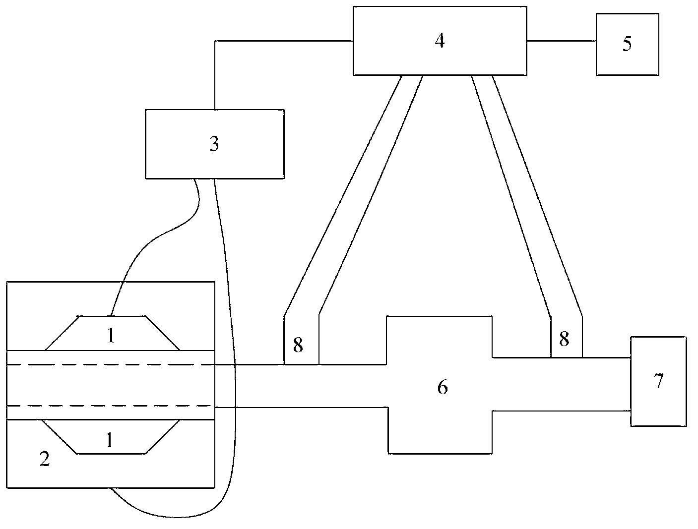
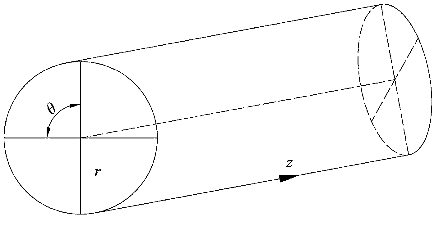
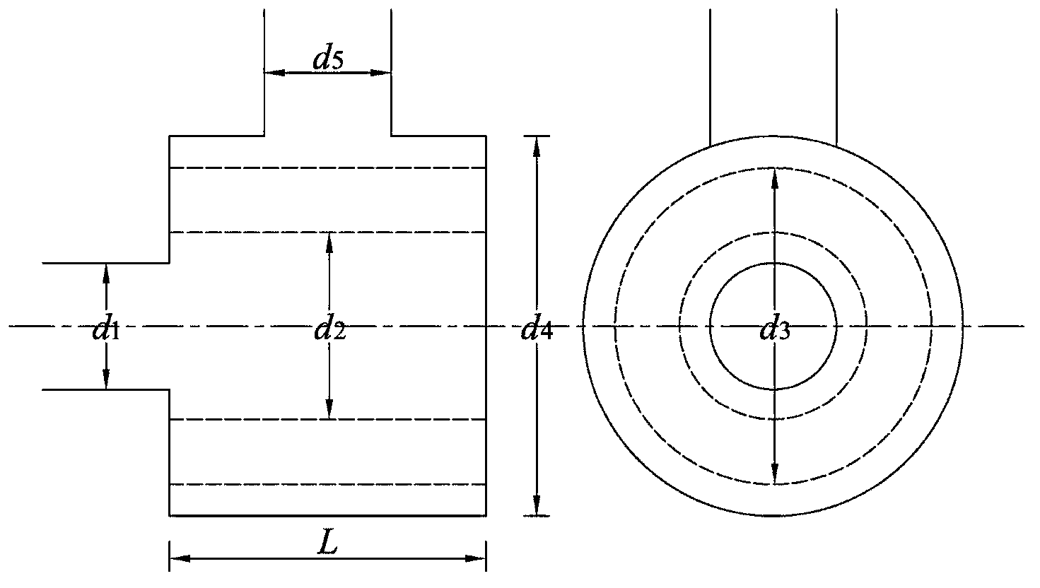
[0022] to combine figure 1 ~5. According to the distribution of the modal nodal line of the cross-section of the muffler inlet and outlet, rigid partitions are arranged on the modal nodal line, and the inlet and outlet pipes are divided into multiple areas on average, and the symmetry of the sound pressure on both sides of the modal nodal line is used to eliminate Specific modal effects, thereby increasing the plane wave cut-off frequency in each region, and broadening the frequency range of asymmetric muffler transmission loss measurement.

[0023] The experimental device for widening the measurement range of asymmetrical muffler transmission loss of the present invention is mainly composed of 1 loudspeaker, 2 sound boxes, 3 power amplifiers, 4 multi-channel data acquisition analyzers, 5 computers, 6 mufflers to be tested, 7 end mufflers and 8 microphones . Dur...


PUM


Abstract

The invention aims to provide a method for measuring transmission loss of an asymmetric pipeline silencer. The method comprises the following steps: a microphone is arranged in one fan-shaped area in an inlet and outlet pipeline, and incident sound pressure and transmission sound pressure of the area are measured; and the prior step is repeated according to the number of partition boards to respectively measure the incident sound pressure and the transmission sound pressure in each fan-shaped area in the inlet and outlet pipeline, and the transmission loss is computed according to the formula disclosed in the specification. According to the method disclosed by the invention, the precision within an inlet and outlet plane wave cut-off frequency range of the conventional measurement method can be met, the silencing performance of the silencer after the frequency is higher than the inlet and outlet plane wave cut-off frequency can be precisely detected, and the problem that the acoustic performance of a large-caliber asymmetric silencer at high frequency can not be accurately forecast is solved.

Description

technical field [0001] The invention relates to a measuring method, in particular to a sound loss measuring method. Background technique [0002] Transmission loss is the difference between the incident sound power level at the inlet of the muffler and the transmitted sound power level at the exit of the muffler. Transmission loss is an attribute of the muffler alone, and has nothing to do with the piping system and noise source. In the design stage of the muffler, the transmission loss is often used as an index to measure the muffler performance. [0003] The existing methods for experimental measurement of muffler transmission loss include acoustic wave decomposition method, two-load method, two-sound-source method and pulse method. The acoustic wave decomposition method is based on the principle of acoustic wave decomposition. The incident sound wave and the transmitted wave are decomposed by the microphone installed in the upstream and downstream pipelines of the muffle...

Claims


Application Information

Patent Timeline
Patent Type & Authority Applications(China)
IPC IPC(8): G01M99/00
Inventor 方智季振林李海龙
Owner HARBIN ENG UNIV
Why Eureka
Try Eureka