Motor grader and control system therefore

a technology of motor graders and control systems, applied in mechanical machines/dredgers, analogue processes for specific applications, instruments, etc., can solve problems such as erroneous cross-slope cuts, one end of the blade being lowered or raised by a significant amount, and affecting the operation of the system, so as to achieve the desired precision and raise and lower the grader blades

Active Publication Date: 2008-01-03
CATERPILLAR TRIMBLE CONTROL TECH
View PDF18 Cites 16 Cited by
  • Summary
  • Abstract
  • Description
  • Claims
  • Application Information

AI Technical Summary

Benefits of technology

[0009]This need is met by a motor grader and a control system for the motor grader in which the manner of controlling the blade position is different when the blade is moved upward or downward than when the blade is maintained at a desired height and inclination. The motor grader has a blade for grading a surface, and first and second hydraulic cylinders for raising and lowering the blade adjacent its first and second ends. First and second hydraulic valves control the flow of hydraulic fluid to the first and second hydraulic cylinders, respectively. An inclinometer is mounted for movement with the blade to provide an inclinometer output indicating the inclination of the blade along its length with respect to horizontal. The control system includes a first hydraulic cylinder position sensor for determining the extended position of the first hydraulic cylinder. The control system further includes a control that is responsive to a control input specifying the desired height and cross slope of the blade, to the hydraulic cylinder position sensor, and to the inclinometer output. The control provides valve control signals to the first and second hydraulic valves. The control provides a first valve control signal to the first hydraulic valve in dependence upon a desired height specified by the control input, and the control provides a second valve control signal to the second hydraulic valve in dependence upon the inclinometer output and upon the cross slope specified by the control input. However, when the blade is to be moved upward or downward, the control provides the second valve control signal to the second hydraulic valve in dependence upon the hydraulic cylinder position sensor such that the second hydraulic cylinder extends and retracts with the first hydraulic cylinder in a way that maintains the cross slope angle of the blade. When the second hydraulic cylinder is controlled in a closed loop manner, the control provides the second valve control signal to said second hydraulic valve in dependence upon the first and the second hydraulic cylinder position sensors.
[0010]The control provides the second valve control signal to the second hydraulic valve in dependence upon the hydraulic cylinder position sensor when the difference between the desired height and the measured height of the blade exceeds a predetermined threshold level. The control system further includes a manual control mechanism to permit the operator to control the control input manually, specifying the desired height and cross slope of the blade. The control system further includes an automated system that provides control signals to the valves in dependence upon the location of the motor grader.
[0011]A method of controlling a motor grader of this type comprises the steps of determining the inclination of the blade, raising or lowering the first end of the blade with a first hydraulic cylinder in response to a control input applied to a controller, and raising or lowering the second end of the blade. When the blade is to be maintained at a desired height, the inclination of the blade is monitored and the second end of the blade is raised or lowered with the second hydraulic cylinder so that the measured inclination of the blade remains constant. When the blade is to be moved upward or downward, however, the position of the first hydraulic cylinder is monitored and the second end of the blade is raised or lowered with the second hydraulic cylinder such that the second hydraulic cylinder moves with the movement of the first hydraulic cylinder. The second hydraulic cylinder may be controlled in either an open loop or a closed loop fashion.
[0012]The method further includes the step of monitoring the position of the first hydraulic cylinder with a sensor that monitors extension and retraction of the cylinder. The method further includes the step of monitoring the position of the second hydraulic cylinder with a sensor that monitors extension and retraction of the cylinder. The method may include the step of providing a control input to the control from a manually actuated control device. Alternatively, the method may include the step of providing a control input to the control from an automated system. The step of providing a control input to the control from an automated system may include the steps of projecting a reference plane of laser light, and a receiving the plane of laser light with a receiver, carried on the motor grader. The step of providing a control input to the control from an automated system may include the step of determining the position of the motor grader and determining the desired height of the first end of the blade and the desired inclination of the blade at the position of the motor grader.
[0013]It is an object of the present invention to provide a motor grader and a control for a motor grader that is capable of raising and lowering the grader blade with desired precision. Other objects and advantages of the invention will be apparent from the following description, the accompanying drawings, and the appended claims.

Problems solved by technology

However, damping produces a time delay in an inclinometer output in a motor grader system that degrades the operation of the system when a change in the elevation of the blade is to be effected.
Because the hydraulic cylinder that is controlled manually or automatically is extended or retracted quickly in such a situation, the inherent time delay in the inclinometer results in one end of the blade being lowered or raised by a significant amount before the inclinometer provides an output indicating a change in inclination.
This, in turn, results in an erroneous cross slope cut during those times when elevational change is effected.

Method used


Image

  • Motor grader and control system therefore
  • Motor grader and control system therefore
  • Motor grader and control system therefore

Examples


Embodiment Construction

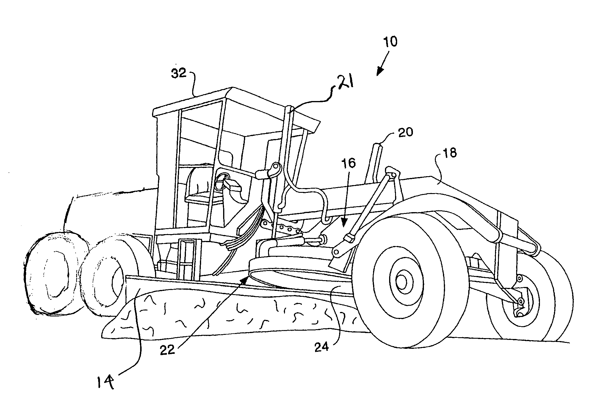
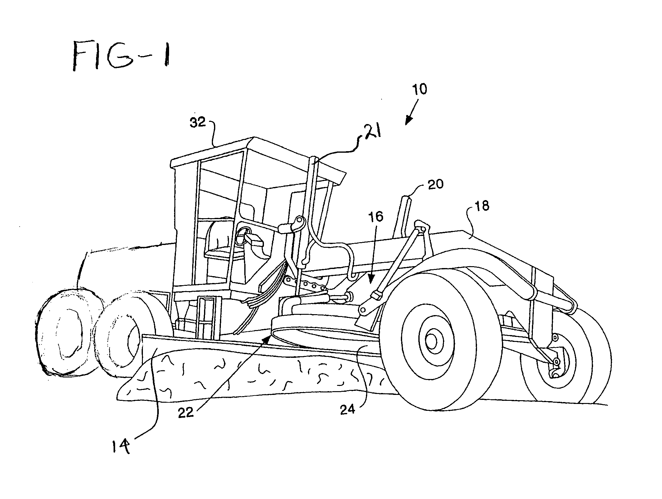
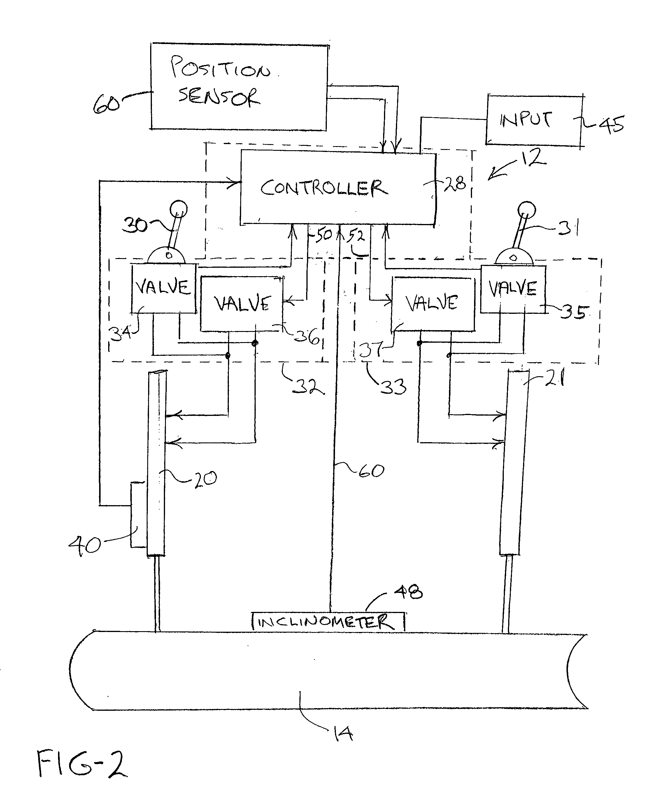
[0017]Reference is made to FIGS. 1 and 2 of the drawings which illustrate the invention. The motor grader 10 includes a control system 12, shown in FIG. 2, for controlling the height of conventional grader blade 14. Blade 14 is part of a blade sub-assembly, indicated generally at 16, that is movably mounted to a frame 18 of the motor grader 10 through first and second individually controllable hydraulic motors or lift cylinders 20 and 21 that are connected between the machine frame 18 and the blade sub-assembly 16. The blade sub-assembly 16 includes a circle and circle draw bar, indicated generally at 22, and a grader blade 14 mounted to the circle. A selectively controllable circle drive (not shown) is mounted to the circle draw bar for rotating the circle and the blade about a generally vertical axis in a known manner. While the blade control system 12 will be described in detail below as applied to the motor grader of FIG. 1, it will be appreciated by those skilled in the art tha...


PUM


Abstract

A motor grader has a control system in which the manner of controlling the blade position differs depending upon whether the blade is to be moved vertically or is to be maintained at a generally constant level and cross slope. First and second hydraulic valves control the flow of hydraulic fluid to the first and second hydraulic cylinders which raise and lower respective ends of the blade. An inclinometer provides an inclinometer output indicating the inclination of the blade along its length with respect to horizontal. The control system includes a first hydraulic cylinder position sensor for determining the extension of the first hydraulic cylinder. The control system further includes a control that is responsive to a control input specifying the desired height and cross slope of the blade, to the first hydraulic cylinder position sensor, and to the inclinometer output. The control provides valve control signals to the first and second hydraulic valves. The control provides a first valve control signal to the first hydraulic valve in dependence upon a desired height specified by the control input, and the control provides a second valve control signal to the second hydraulic valve in dependence upon the inclinometer output and upon the cross slope specified by the control input. However, when the blade is to be moved upward or downward with the retraction or extension of the first cylinder, the control provides the second valve control signal to the second hydraulic valve in dependence upon the first hydraulic cylinder position sensor such that the second hydraulic cylinder retracts and extends with the first hydraulic cylinder, maintaining the cross slope angle of the blade as a constant.

Description

CROSS-REFERENCE TO RELATED APPLICATIONS[0001]Not applicable.STATEMENT REGARDING FEDERALLY SPONSORED RESEARCH OR DEVELOPMENT[0002]Not applicable.BACKGROUND OF THE INVENTION[0003]The present invention relates generally to a motor grader and a control system for a motor grader of the type in which the vertical position of the grader blade is controlled by a pair of hydraulic cylinders. More particularly, the present invention relates to such a motor grader and control system in which the extension or retraction of one hydraulic cylinder of the pair follows that of the other hydraulic cylinder when vertical movement of the blade is to be effected, thereby maintaining the cross slope angle.[0004]Motor graders are used to alter the contours of construction sites and road beds. Motor graders typically include a work implement, such as a surface-altering blade, that is movably connected to a frame of the grader by a structure including a pair of independently controlled hydraulic cylinders....

Claims


Application Information

Patent Timeline
Patent Type & Authority Applications(United States)
IPC IPC(8): E02F3/00
CPCE02F3/845E02F3/765
Inventor ZACHMAN, MARK
Owner CATERPILLAR TRIMBLE CONTROL TECH
Why Eureka
Try Eureka