Transformer framework preventing winding lead wire from crossing

A technology of transformer skeleton and winding leads, which is applied to the parts of transformer/inductor, transformer/inductor coil/winding/connection, electrical components, etc., which can solve the problem of inability to realize fully automatic production of transformers, uncontrollable quality of transformers, and uneven quality unevenness and other problems, to promote green production, avoid direct cross-contact, and ensure consistency

Inactive Publication Date: 2019-01-29
DONGGUAN AOHAI TECH CO LTD
View PDF4 Cites 2 Cited by
  • Summary
  • Abstract
  • Description
  • Claims
  • Application Information

AI Technical Summary

Problems solved by technology

[0004] Therefore, in the production of the prior art, a layer of insulator is usually added to the stressed part of the secondary coil for protection. The insulator can be an insulating sleeve or an insulating tape. It is set or wrapped on the secondary coil of the transformer, which has the following defects: (1) due to the differences in the individual experience of the workers, the quality of the processed transformer is uncontrollable, and the quality is uneven, resulting in the outflow of defective products; (2) the transformer cannot be realized Fully automated production, poor production efficiency and low production capacity; (3) High labor costs

Method used


Image

  • Transformer framework preventing winding lead wire from crossing
  • Transformer framework preventing winding lead wire from crossing
  • Transformer framework preventing winding lead wire from crossing

Examples


Embodiment 1

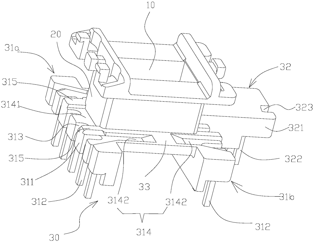
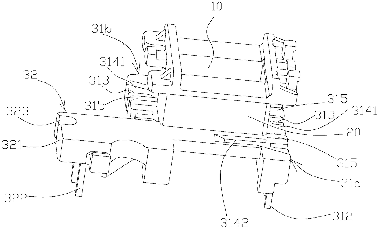
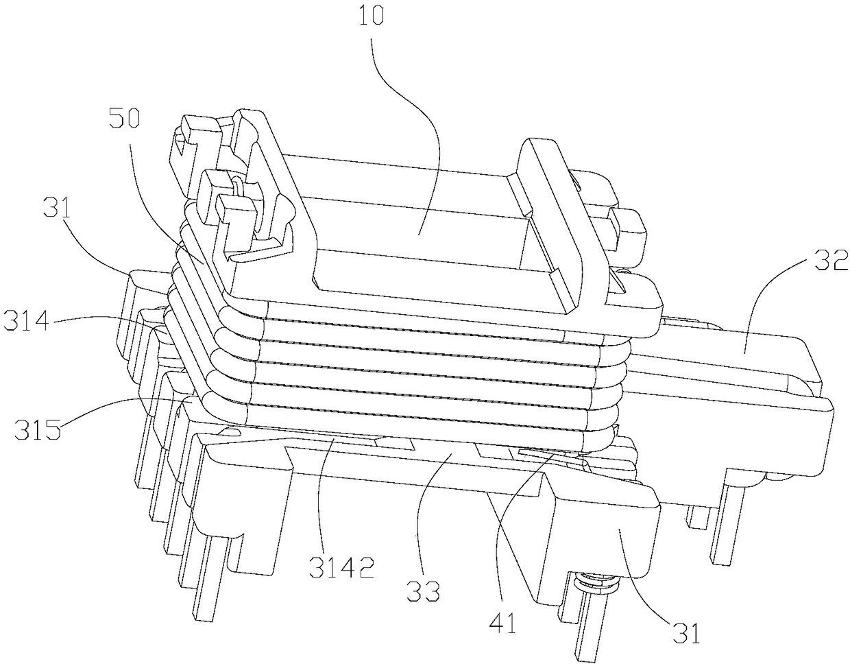
[0030] Such as Figure 1-5 As shown, in this specific embodiment, the transformer bobbin includes a magnetic core slot 10 that runs through longitudinally, an upper layer of the bobbin vertically arranged on the top periphery of the magnetic core slot 10, a winding bobbin 30 vertically arranged on the bottom periphery of the magnetic core slot 10, and the bobbin The upper layer, the winding bobbin 30 and the outer wall of the magnetic core slot 10 form a winding slot 20 for winding the primary coil 40 and the secondary coil 50 ; the secondary coil 50 is wound outside the primary coil 40 . Wherein, the winding bobbin 30 includes a primary bobbin 31 and a secondary bobbin 32; the primary bobbin 31 includes a first primary bobbin 31a and a second primary bobbin 31b, the first primary bobbin 31a is arranged on one side of the magnetic core slot 10, the second The two primary frames 31b and the secondary frame 32 connected to the inner end of the second primary frame 31b and extend...

Embodiment 2

[0038] Such as Figure 6-8 As shown, in this specific embodiment, the transformer skeleton of the invention includes a magnetic core slot 10 that runs through transversely, and the same side at both ends of the magnetic core slot 10 is respectively provided with a winding bobbin 30 in parallel, and the outer wall of the magnetic core slot 10 and the winding bobbin 30 A winding slot 20 for winding the primary coil 40 and the secondary coil 50 is formed. Wherein, the winding frame 30 includes a primary frame 31 and a secondary frame 32, the primary frame 31 includes a first primary frame 31a, a second primary frame 31b, the first primary frame 31a is arranged at one end of the winding groove 20, and the second primary frame 31b and the secondary skeleton 32 connected to the second primary skeleton 31b and extending vertically outward along the length direction of the second primary skeleton 31b form an L-shaped skeleton, and the L-shaped skeleton is arranged at the other end of ...


PUM


Abstract

The invention provides a transformer framework preventing a winding lead wire from crossing. The transformer framework comprises a magnetic core groove and a winding framework body arranged at the endof the magnetic core groove; the outer wall of the magnetic core groove and the winding framework body form a winding groove for winding a primary coil and a secondary coil; the winding framework body comprises a primary framework body and a secondary framework body; the primary framework body extends outwards to be provided with a plurality of primary wire hanging columns distributed at intervals, each primary wire hanging column is provided with a primary pin perpendicular to the primary wire hanging column, and a primary wire crossing groove is formed in a gap of every two primary wire hanging columns; the primary framework body is provided with primary wire guiding grooves flush with or lower than the primary framework body and communicated with the primary wire crossing grooves, so that a lead wire of the primary coil winding the winding groove passes through the primary wire guiding grooves in a horizontal or obliquely-downward wire outlet mode, penetrates through the primary wire crossing grooves, bypasses the primary wire hanging columns and finally winds the primary pins, and a height difference is formed between the lead wire of the primary coil and the secondary coil winding the periphery of the lead wire. The transformer framework can achieve the full-automated production of a transformer.

Description

technical field [0001] The invention relates to a transformer for a charger, in particular to a transformer frame for preventing crossing of winding lead wires. Background technique [0002] The transformer is an important electrical device in the power output distribution system. It mainly includes a magnetic core, a transformer skeleton, a primary coil and a secondary coil, and uses the principle of electromagnetic induction to transmit electric energy. The primary coil is used to connect with the AC power supply and is wound on the winding slot of the transformer skeleton. The secondary coil is used to output the induced potential and is wound outside the primary coil. By setting multiple coil windings on the secondary coil, the output potential can be changed. potential level. However, for vertical transformer bobbins, such as Figure 9 As shown, the lead wire 41 of the primary coil and the bottom layer of the secondary coil 50 are attached to the surface of the primary...

Claims


Application Information

Patent Timeline
Patent Type & Authority Applications(China)
IPC IPC(8): H01F27/30
CPCH01F27/306
Inventor 刘昊白中涛胡隆彪王金标
Owner DONGGUAN AOHAI TECH CO LTD
Why Eureka
Try Eureka