
Wind-driven generator stator and rotor sleeving tool

A stator-rotor and wind-driven motor technology, applied in wind power generation, centering/balancing rotors, etc., can solve problems such as poor effects, and achieve the possible effects of improving uniformity, small size, and reducing rotor deformation

Pending Publication Date: 2019-01-29
卓弢机器人盐城有限公司
View PDF0 Cites 1 Cited by
  • Summary
  • Abstract
  • Description
  • Claims
  • Application Information

AI Technical Summary

Problems solved by technology

[0003] The technical problem to be solved by the present invention is: to overcome the technical problem of the poor effect of the retractable suit structure in the prior art, and to provide a wind motor stator rotor suit tooling

Method used


Image

  • Wind-driven generator stator and rotor sleeving tool
  • Wind-driven generator stator and rotor sleeving tool
  • Wind-driven generator stator and rotor sleeving tool

Examples


Embodiment Construction

[0021] The present invention is described in further detail now in conjunction with accompanying drawing. These drawings are all simplified schematic diagrams, which only illustrate the basic structure of the present invention in a schematic manner, so they only show the configurations related to the present invention.

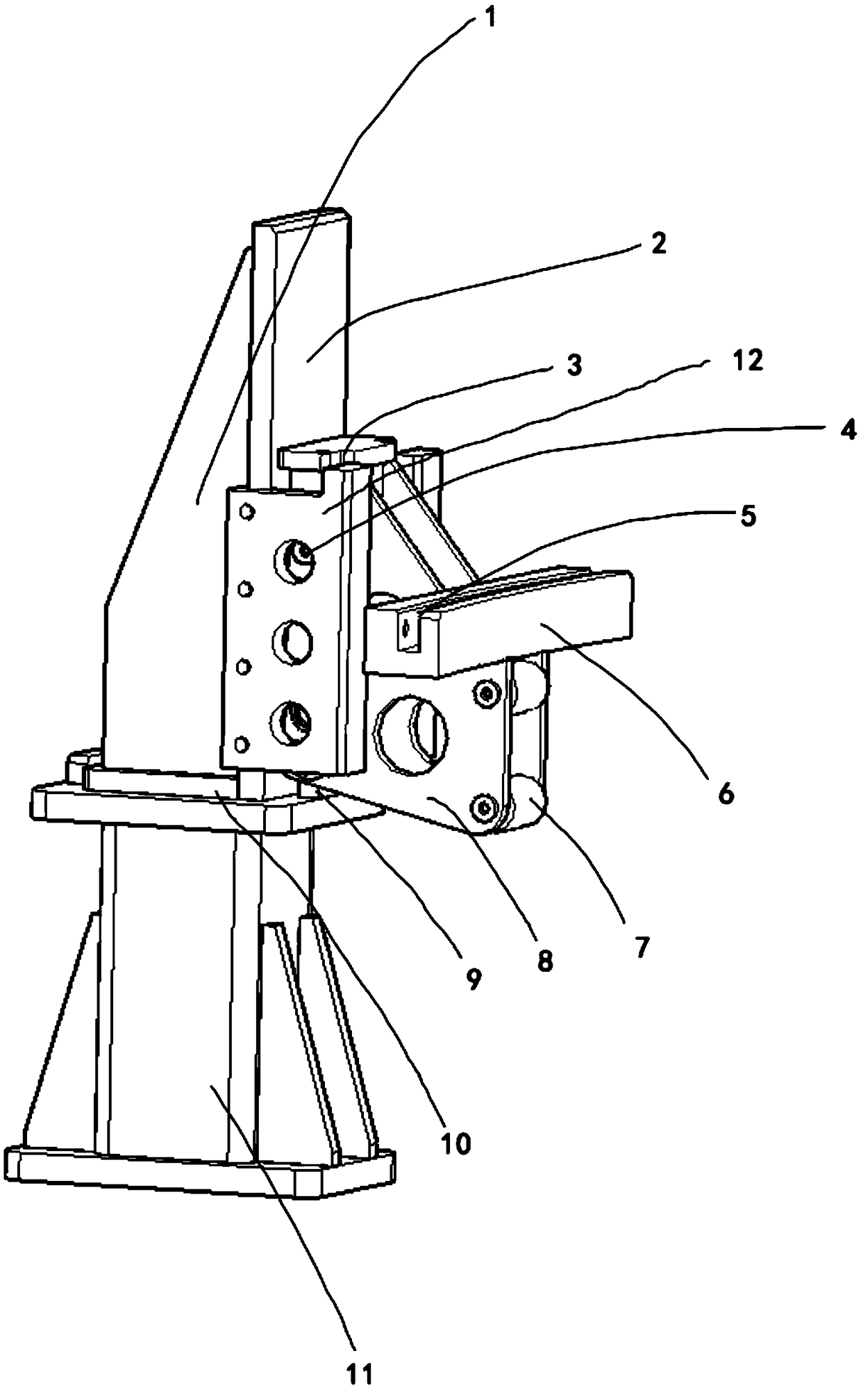
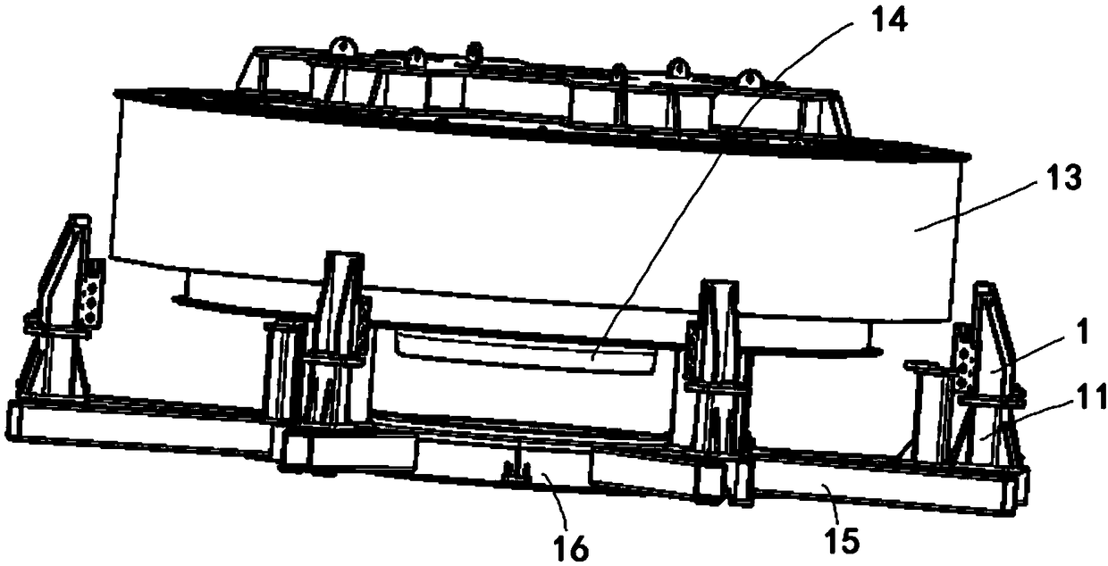
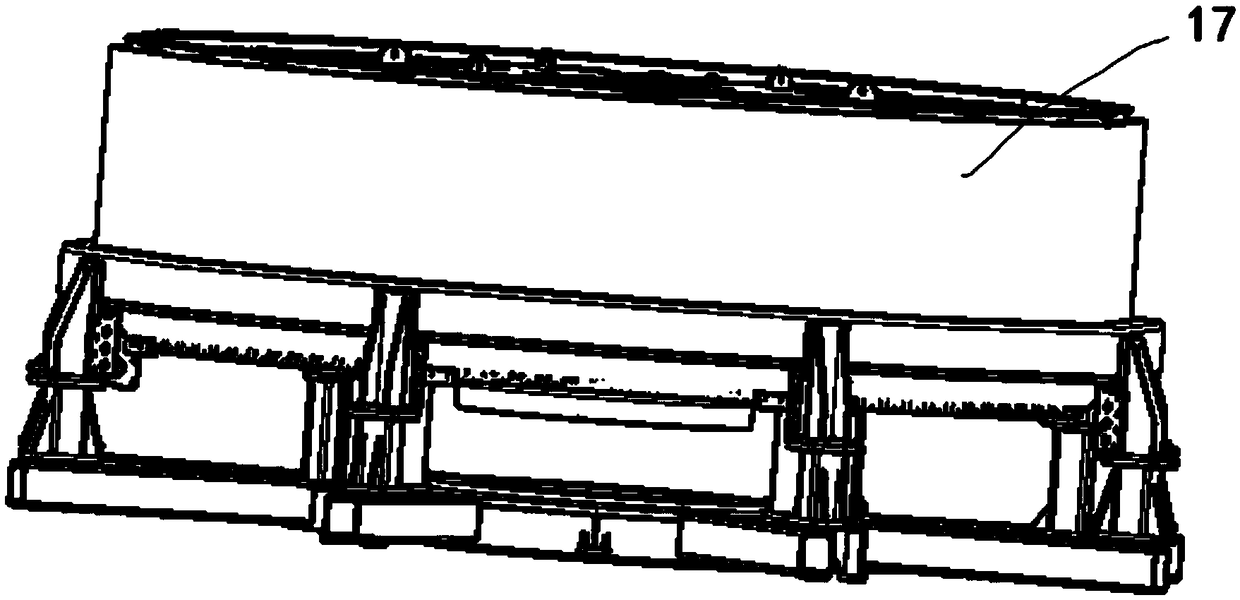
[0022] In the figure: 1. Rib; 2. Guide surface; 3. Sliding connector; 4. Pulley A; 5. Arc groove; 6. Rotor connector; 7. Pulley B; 8. Connecting plate; 9. Positioning plate ; 10, support plate; 11, guide connecting seat; 12, guide rail piece; 13, stator; 14, rotating connecting column; 15, connecting arm; 16, stator concentric disk;

[0023] Such as figure 1 , figure 2 , image 3 , a wind motor stator rotor suit tooling, which includes a stator bracket, the stator bracket includes a stator concentric disk, the stator concentric disk is centered and connected with a stator core through a rotating connecting column, and the peripheral annular array of the ce...


PUM


Abstract

The invention relates to a wind-driven generator stator and rotor sleeving tool, which comprises a stator bracket and a rotor connector, wherein the stator bracket and the rotor connector are connected by means of a guiding device, the stator bracket comprises a stator concentric disc, the stator concentric disc is connected with a stator core by means of a rotary connecting column, a plurality ofconnecting arms are arranged on the periphery of a connecting column in an annular array, and two groups of guide rail pieces in mirror symmetry are fixed to the end part of each connecting arm; theguiding device comprises a guiding surface, the guide rail pieces are fixed to the two transverse sides of the guiding surface by means of one edges in the width direction, and the other edge of the guide rail pieces are provided with limiting protruding strips; the guiding device further comprises a sliding support fixed on a rotor outer shell, the sliding support comprises an arc-shaped rotor connector, a stator contactor is fixedly connected to the lower part of the rotor connector, and the stator contactor comprises a plurality of sliding contact surfaces used for being in contact with thesurface of a stator; and the stator contactor and the rotor connector are both fixed on a sliding connector, and a plurality of limiting sliding blocks are symmetrically arranged on the sliding connector.

Description

technical field [0001] The invention relates to a stator rotor suit tooling of a wind power motor, which belongs to the field of wind power generator manufacturing equipment. Background technique [0002] There is a very thin working gap between the stator and the rotor of the wind turbine, because the inner wall of the rotor is provided with a magnet block with strong attraction, it is easy to cause the rotor to be adsorbed to the stator during the assembly process, and the assembly failure occurs , and the traditional solution is to use the relevant pre-fixed guide to realize the package by using the expansion and contraction of the guide. However, because the length of the guide rail and the cylinder of the guide itself are relatively long, a certain amount of bending deformation will occur, so it is easy to occur due to deformation. After the rotor and stator are assembled, the gap uniformity is poor. In the later rotation process, the positioning and the rotor are prone...

Claims


Application Information

Patent Timeline
Patent Type & Authority Applications(China)
IPC IPC(8): H02K15/16
CPCH02K15/16Y02E10/72
Inventor 严立兵胡跃葛中雨
Owner 卓弢机器人盐城有限公司
Learn More