
An information transmission method, network side equipment and terminal

A transmission method and terminal technology, applied in the field of communication, can solve the problems of data packet transmission errors and large packet header overhead, and achieve the effects of improving reliability, reducing header overhead, and ensuring correctness

Active Publication Date: 2022-04-29
CHINA MOBILE COMM LTD RES INST +1
View PDF2 Cites 0 Cited by
  • Summary
  • Abstract
  • Description
  • Claims
  • Application Information

AI Technical Summary

Problems solved by technology

[0005] In the prior art, if the data packet is sent according to the reflective QoS mechanism, the overhead of the packet header when the QoS flow is mapped to the DRB will be large, and the transmission error of the data packet may occur

Method used


Image

  • An information transmission method, network side equipment and terminal
  • An information transmission method, network side equipment and terminal
  • An information transmission method, network side equipment and terminal

Examples


Embodiment Construction

[0105] Exemplary embodiments of the present disclosure will be described in more detail below with reference to the accompanying drawings. Although exemplary embodiments of the present disclosure are shown in the drawings, it should be understood that the present disclosure may be embodied in various forms and should not be limited by the embodiments set forth herein. Rather, these embodiments are provided for more thorough understanding of the present disclosure and to fully convey the scope of the present disclosure to those skilled in the art.

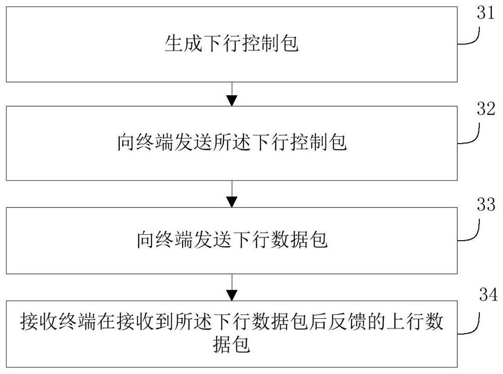
[0106] Such as image 3 As shown, an embodiment of the present invention provides a method for transmitting information, including:

[0107]Step 31, generate a downlink control packet, the downlink control packet carries a QoS flow identifier and a reflection identifier, the Qos flow identifier is a QoS flow identifier added when the downlink data packet from the application layer is mapped into a Qos flow, and the reflection The ...


PUM


Abstract

Embodiments of the present invention provide an information transmission method, network-side equipment, and a terminal. The method includes: generating a downlink control packet, the downlink control packet carrying a QoS flow identifier and a reflection identifier, and the Qos flow identifier is obtained from an application The QoS flow identifier added when the downlink data packet of the layer is mapped to a Qos flow, and the reflection identifier indicates whether to use the data wireless bearer used for sending the downlink data packet when the terminal receives the downlink data packet and feeds back the uplink data packet The DRBs with the same DRB perform the identification of the uplink data packet feedback; and send the downlink control packet to the terminal. The scheme of the invention reduces the overhead of the packet header when the Qos flow is mapped to the DRB, and improves the reliability of information transmission.

Description

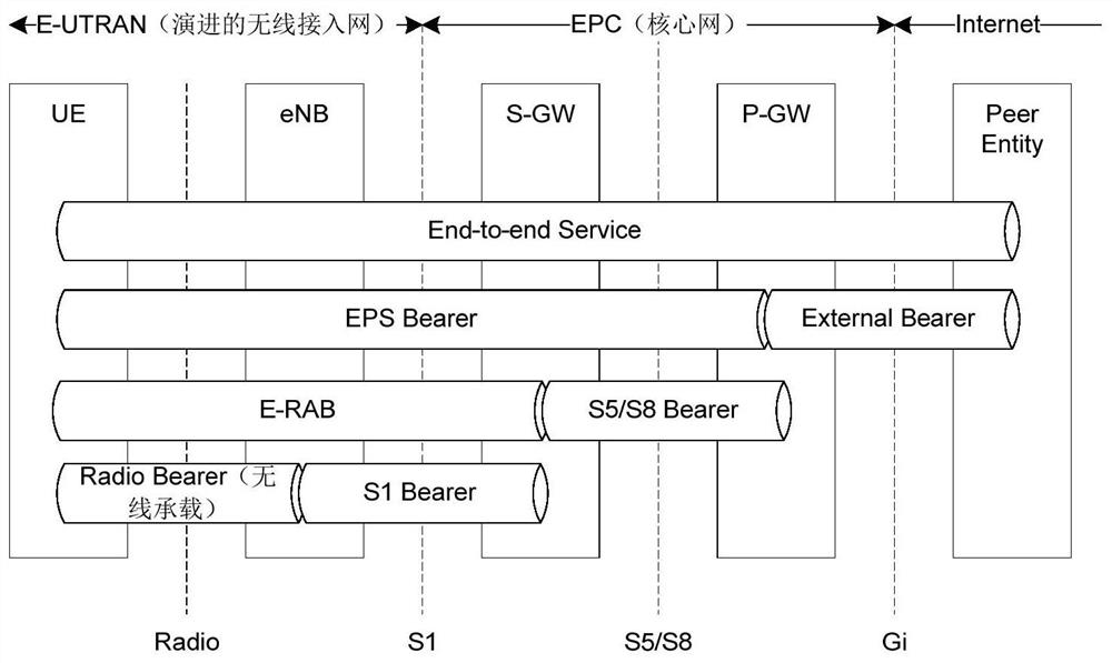
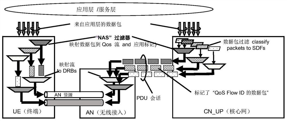
technical field [0001] The present invention relates to the technical field of communication, and in particular to an information transmission method, network side equipment and terminal. Background technique [0002] The current LTE system adopts an end-to-end QoS management mechanism and differentiated services to meet the QoS requirements of different services. QoS is completed in the form of multiple layers, and the QoS management of the entire LTE network is achieved through figure 1 to achieve. E-RAB (evolved Radio Access Bearer, evolved radio access bearer) and Radio bearer (radio bearer) are the smallest units for QoS management on the EPS side and the RAN (radio access layer) side, respectively. EPS (Evolved Packet System) is a complete evolved packet system, which is composed of wireless network (LTE), core network (EPC) and user terminal (UE). [0003] Such as figure 2 As shown, in 5G, the downlink data packet (IP flow) first maps the downlink data packet fro...

Claims


Application Information

Patent Timeline
Patent Type & Authority Patents(China)
IPC IPC(8): H04L47/24H04L47/2491
CPCH04L47/24H04L47/2491H04W28/00H04W28/0268
Inventor 王莹莹孙军帅黄学艳韩星宇易芝玲
Owner CHINA MOBILE COMM LTD RES INST
Learn More