Panoramic video transmission method, transmission device and transmission system

A technology of panoramic video and transmission method, applied in the field of panoramic video transmission system and computer-readable storage medium, can solve the problems of video block acquisition error, mixed bit rate boundary effect, affecting user experience, etc., so as to improve video quality, The effect of reducing quality fluctuations

Inactive Publication Date: 2019-01-29
PEKING UNIV
View PDF6 Cites 17 Cited by
  • Summary
  • Abstract
  • Description
  • Claims
  • Application Information

AI Technical Summary

Problems solved by technology

[0005] However, there are still challenges in providing high-quality chunk-based delivery: (1) Video chunk acquisition error
To obtain future video content in advance, the client needs to predict the user's viewing direction. If the prediction is wrong, the client will not download some video segments. If this part of the video content is needed during actual playback, this part of the content will be missing. Affect user experience; (2) video playback freezes
Due to the immediacy of the prediction of the user's viewing orientation, that is, the accuracy of the prediction of the user's orientation for a long time in the future will be extremely reduced, so the playback buffer of the video is very small (for example, 3 seconds), and it is easy to happen in the case of a small buffer Video playback freezes; (3) Mixed bit rates lead to boundary effects
Since the block-based transmission method needs to divide the video in space, when the client selects the video content, the video may have obvious borders or inconsistent quality when rendering due to different bit rates.

Method used


Image

  • Panoramic video transmission method, transmission device and transmission system
  • Panoramic video transmission method, transmission device and transmission system
  • Panoramic video transmission method, transmission device and transmission system

Examples


Embodiment Construction

[0082] In order to understand the above-mentioned purpose, features and advantages of the present invention more clearly, the present invention will be further described in detail below in conjunction with the accompanying drawings and specific embodiments. It should be noted that, in the case of no conflict, the embodiments of the present application and the features in the embodiments can be combined with each other.

[0083] In the following description, many specific details are set forth in order to fully understand the present invention. However, the present invention can also be implemented in other ways different from those described here. Therefore, the protection scope of the present invention is not limited by the specific details disclosed below. EXAMPLE LIMITATIONS.

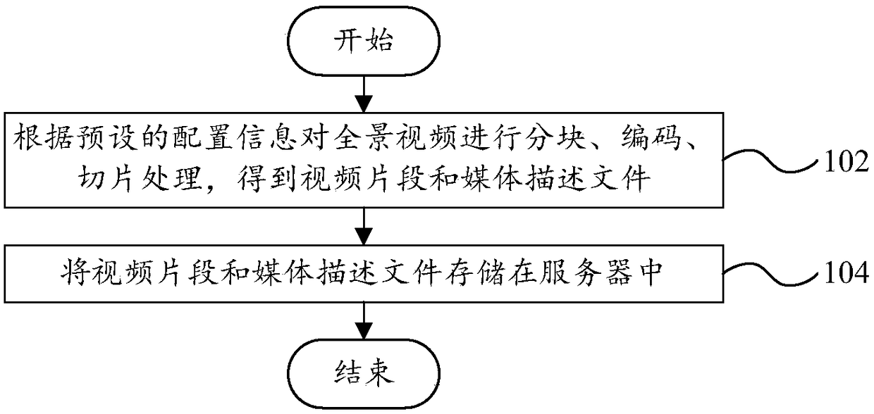
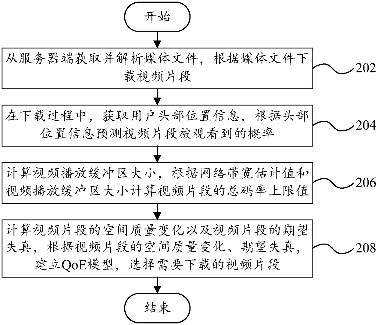
[0084] Such as figure 1 Shown is a schematic flow chart of a panoramic video transmission method according to an embodiment of the first aspect of the present invention. Among them, the transmissio...


PUM


Abstract

The invention provides a panoramic video transmission method, a transmission device and a transmission system, wherein the panoramic video transmission method is applied to a client and comprises thesteps of acquiring a media file from a server end and analyzing the file, and downloading video segments according to the media file; in a loading process, acquiring head position information of a user, and predicating viewing probability of the video segments according to the head position information; calculating the size of a video playing buffering area, and calculating a total code rate upperlimit of the video segments according to the estimated network bandwidth and the size of the video playing buffering area; calculating the spatial quality change of the video segments and the expected distortion of the video segments, establishing a QoE model according to the spatial quality change and the expected distortion of the video fragments, and selecting the to-be-downloaded video fragments. The panoramic video transmission method, the transmission device and the transmission system realize technical effects of reducing data volume in panoramic video transmission, improving video quality, reducing spatial quality fluctuation and lags in video playing.

Description

technical field [0001] The present invention relates to the field of multimedia technology, in particular to a panoramic video transmission method, a panoramic video transmission device, a panoramic video transmission system, a computer device, and a computer-readable storage medium. Background technique [0002] With the development of multimedia technology, virtual reality technology (VR) has received extensive attention from industry and academia. Among them, applications of panoramic video, such as 360-degree video and omnidirectional video, have been widely used. [0003] The data volume of virtual reality video is usually very large, which makes the compression bit rate and network transmission of panoramic video the biggest challenge. For example, a panoramic video with a resolution of 4Kx2K and mapped in ERP mode can reach a bit rate of 15Mbps to 20Mbps after compression and encoding. The characteristics of high resolution and high bit rate of panoramic video hinde...

Claims


Application Information

Patent Timeline
Patent Type & Authority Applications(China)
IPC IPC(8): H04N21/845H04N21/2662H04N21/858H04N21/262H04N21/6587H04N21/234
CPCH04N21/234H04N21/26216H04N21/2662H04N21/6587H04N21/8456H04N21/8586
Inventor 谢澜张行功郭宗明
Owner PEKING UNIV
Why Eureka
Try Eureka