
Hole flanging die structure and stamping method

A technology of turning holes and molds, which is applied in the directions of forming tools, manufacturing tools, metal processing equipment, etc., can solve the problems of large deformation, poor flatness of the straight wall of the flanging hole of the round tube, poor appearance quality, etc. The effect of good flatness, good appearance and high quality

Pending Publication Date: 2019-02-01
ZHUHAI GREE PRECISION MOLD CO LTD +1
View PDF0 Cites 0 Cited by
  • Summary
  • Abstract
  • Description
  • Claims
  • Application Information

AI Technical Summary

Problems solved by technology

[0004] Therefore, the technical problem to be solved by the present invention is to overcome the defects of poor flatness, poor appearance quality and large deformation of the flanging straight wall of the round pipe flanging hole in the prior art, thereby providing a processed flanging hole with high quality The hole-turning die structure and stamping method

Method used


Image

  • Hole flanging die structure and stamping method
  • Hole flanging die structure and stamping method
  • Hole flanging die structure and stamping method

Examples


Embodiment 1

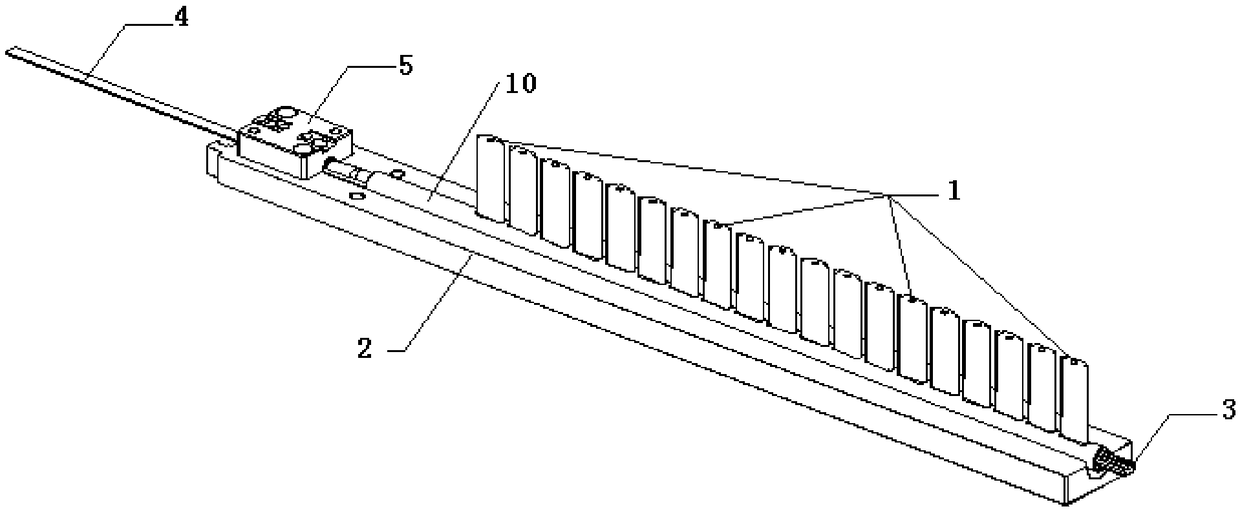
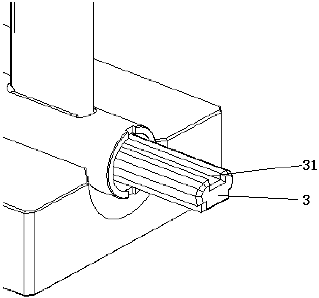
[0061] Such as figure 1 -7 shows a specific embodiment of a hole turning mold structure, including a lower template 2 , a first mandrel 3 and a second mandrel 4 . The first end of the first mandrel 3 is fixed on the fixed block 5, the second end of the first mandrel 3 is suspended, and the lower template 2 is equipped with a fixed block matching the shape of the fixed block 5. Cavity, the fixed block 5 is installed in the fixed block installation cavity and fixed by inserting a pin, the lower template 2 is provided with a support groove 8, and the length direction of the support groove 8 is parallel to the length direction of the first mandrel 3 Setting, in this embodiment, the surface of the support groove 8 is an arc-shaped groove that matches the shape of the lower surface of the round tube 10, and the round tube 10 is sleeved behind the first mandrel 3 to connect with the support The bottom of the groove 8 is in contact. The first mandrel 3 is provided with a groove 31 c...

Embodiment 2

[0071] This embodiment provides a punching method, using the punching die structure provided in Embodiment 1 to punch and punch a tubular structure, including the following steps:

[0072] In the installation step of the tubular structure, the tubular structure is sleeved on the outside of the fixed first mandrel 3 and supported by the lower formwork 2; the second mandrel 4 is inserted into the tubular structure so that the second expansion of the second mandrel 4 The surface cooperates with the first expansion surface of the first mandrel 3, so that the side walls on both sides of the groove 31 of the first mandrel 3 closely fit the inner wall of the tubular structure;

[0073] In the stamping step, the punch 1 of the stamping structure moves downward, the punch 1 passes through the tubular structure and forms a flanging hole on the tubular structure and is supported by the groove 31 of the first mandrel 3, and the punch 1 of the stamping structure moves upward Exit the tubul...


PUM


Abstract

The invention provides a hole flanging die structure and a stamping method. The hole flanging die structure is used for stamping and hole flanging of a tubular structure, and comprises a lower die board, a first mandrel fixed to the lower die board, and a second mandrel provided with a second expansion face, the first mandrel is suitable for being sleeved with the tubular structure and provided with a groove corresponding to a punch of a stamping structure, and a first expansion face, and after the second mandrel is inserted into the tubular structure, the second expansion face and the first expansion face are in expansion fit, so that the side walls of two sides of the groove of the first mandrel are tightly attached to the inner wall of the tubular structure. The hole flanging die structure not only ensures tight attachment with the tubular structure during hole flanging, but also ensures the effect that the tubular structure can be smoothly taken down after hole flanging is finished, and machined flanging holes are good in straight wall flatness, good in appearance quality and high in quality.

Description

technical field [0001] The invention relates to the technical field of collecting pipe processing, in particular to a punching die structure and a stamping method. Background technique [0002] The header in the air conditioner is one of the four important components of the refrigeration system. Fluorine is compressed by the compressor to produce high-temperature and high-pressure gas, which turns into a low-temperature and high-pressure liquid after cooling and condensing through the condenser, and enters the header for collecting And shunt, because it has high heat exchange efficiency and extremely low energy loss, it is widely used. [0003] Its shape is a thin-walled straight-through round tube made of hard aluminum alloy. On the highest point of the cross section, a number of long flanging holes are evenly distributed along the length direction. The flat tube must be firmly fixed in the hole to closely match it and ensure good sealing. The conventional stamping structu...

Claims


Application Information

Patent Timeline
Patent Type & Authority Applications(China)
IPC IPC(8): B21D37/10B21D19/08
CPCB21D19/088B21D37/10
Inventor 赵佳聂文广蔡国旗黄泽坚陈明星
Owner ZHUHAI GREE PRECISION MOLD CO LTD
Learn More