Spark shield protection device for electromechanical cutting machine

A protective device and cutting machine technology, which is applied to the attachment of sawing machines, metal sawing equipment, metal processing equipment, etc., can solve the problems of sparks splashing everywhere, affecting the surrounding environment, and not being able to collect sparks and dust, etc. The effect of flexibility and practicality

Inactive Publication Date: 2019-02-01
于秋林
View PDF0 Cites 0 Cited by
  • Summary
  • Abstract
  • Description
  • Claims
  • Application Information

AI Technical Summary

Problems solved by technology

[0005] In order to solve the above-mentioned technical problems, the present invention provides a spark blocking protection device for electromechanical cutting machines to solve the problem of some existing manipulator pressure cutting machines. Due to the rotating cutting characteristics of the cutting saw blade, the generated sparks will fly towards the operator, and the protective cover on the saw blade cannot collect the spark dust after falling. After the cutting is completed, the sparks will fly everywhere. Yes, it is a problem that affects the surrounding environment

Method used


Image

  • Spark shield protection device for electromechanical cutting machine
  • Spark shield protection device for electromechanical cutting machine
  • Spark shield protection device for electromechanical cutting machine

Examples


Embodiment

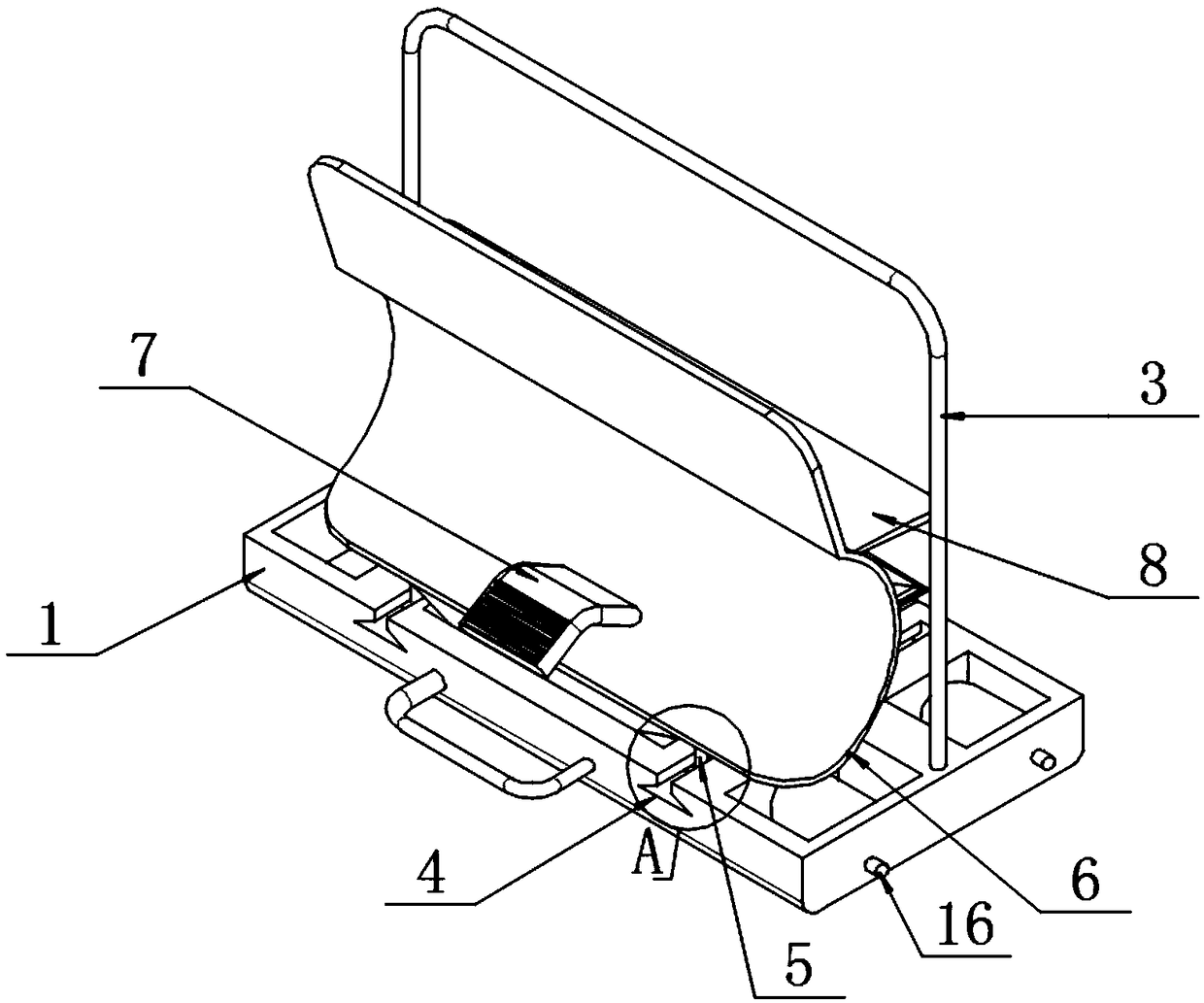
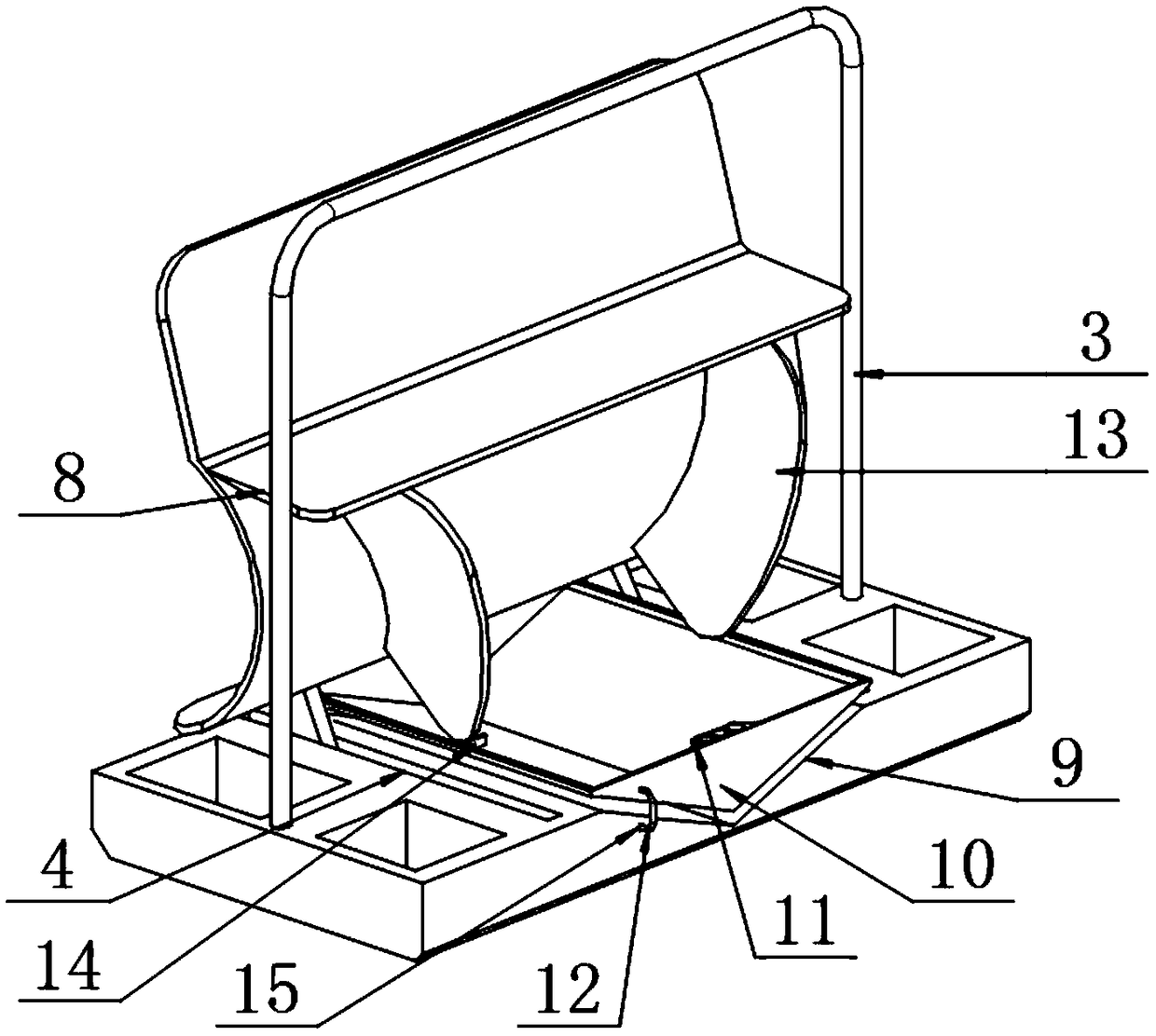
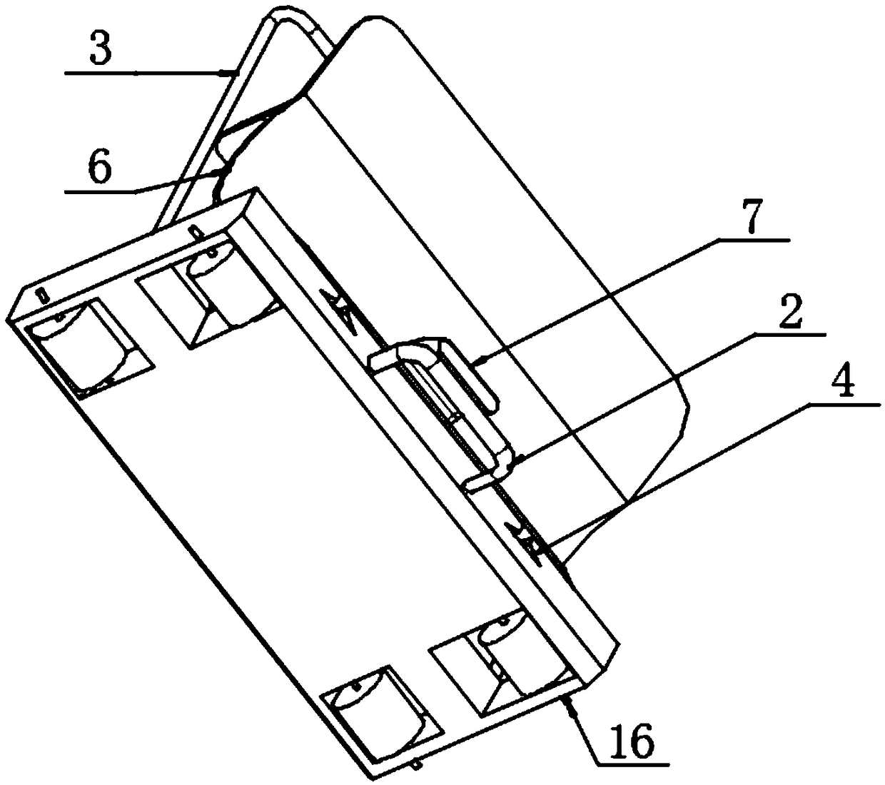
[0030] as attached figure 1 to attach Figure 8 Shown:

[0031] The invention provides a spark shielding protection device for an electromechanical cutting machine, which includes: a base plate 1, a pressing handle 2, a handle 3, a first chute 4, a sliding rod 5, a protective plate 6, a pedal 7, a top Guard plate 8, placement slot 9, storage compartment 10, grip seat 11, guide rod 12, side guard plate 13, push plate 14, sliding hole 15 and rotating shaft 16; structure, and a handle 3 with a U-shaped elbow structure is vertically installed on the top surface of the base plate 1; the left and right sides of the top surface of the base plate 1 are provided with a first The chute 4, and the protective plate 6 is slidably fitted on the first chute 4 through the two left and right slide bars 5 welded at the bottom; the pedal 7 is welded on the outside of the protective plate 6 in an inclined manner, and A top guard plate 8 with a rectangular plate structure is also welded on the ...


PUM


Abstract

The invention provides a spark shield protection device for an electromechanical cutting machine. The spark shield protection device comprises a top protection plate, a storage groove, a containing cabin, a hand gripping seat, a guide rod, side protection plates, a push plate, a sliding hole and a rotating shaft. A pressing handle of a U-shaped structure is mounted on the front end face of a baseplate. A lifting handle of a U-shaped bent pipe structure is vertically mounted on the top face of the base plate. First sliding grooves are formed in the left side and the right side of the top faceof the base plate, wherein the first sliding grooves are each of a swallow-tail-shaped structure. The device can be trodden to be rotated and lifted; the front end is located the edge of the cutting machine, the protection distance is reduced, and flexibility and practicability are further improved; in addition, the containing cabin which can be adjusted to move forwards along with a protection plate is mounted at the front side of the device, and the top protection plate and the side protection plates are mounted at the top side of the containing cabin and the rear end face of the protectionplate, so that ash splashed in the cutting process can be collected; and therefore, the certain ash collection function is achieved, and thus, the problem that the splashing ash influences the surrounding working environment can be solved.

Description

technical field [0001] The invention belongs to the technical field of protection devices for electromechanical cutting machines, and more specifically relates to a spark blocking protection device for electromechanical cutting machines. Background technique [0002] Cutting machines are distinguished from cutting materials, and are divided into metal material cutting machines and non-metallic material cutting machines. [0003] Metal material cutting machines are divided into flame cutting machines, plasma cutting machines, laser cutting machines, water jet cutting machines, etc. Among them, electromechanical cutting machines are widely used in the machinery industry. This cutting machine has a cutting saw blade with a hand-pressed handle at one end , the other end is the workpiece placement platform. When in use, press the handle with your hand to make the saw blade cut to the workpiece, and complete the cutting and segmentation work on the workpiece. [0004] According t...

Claims


Application Information

Patent Timeline
Patent Type & Authority Applications(China)
IPC IPC(8): B23D59/00
CPCB23D59/006
Inventor 于秋林
Owner 于秋林
Why Eureka
Try Eureka