Four-joint plane robot

A four-joint, robot technology, used in manipulators, program-controlled manipulators, manufacturing tools, etc., can solve the problems of reducing the rigidity and accuracy of the robot, the excessive moment of inertia of the robot, and the limited rotation range of the robot, so as to improve the rigidity and operation of the robot. Easy maintenance and compact structure

Pending Publication Date: 2019-02-01
EFORT INTELLIGENT EQUIP CO LTD
View PDF2 Cites 3 Cited by
  • Summary
  • Abstract
  • Description
  • Claims
  • Application Information

AI Technical Summary

Problems solved by technology

[0003] Aiming at the shortcomings of the configuration of the transmission SCARA robot, the invention patent with the Chinese patent application number CN201710380194.6 discloses an upgraded drive mechanism and a planar joint robot, which changes the linear motion of the end of the SCARA to the linear up and down motion of the first axis of the robot, expanding the The range of motion, in order to maintain the overall rigidity, the ball screw is placed behind, resulting in an offset between the rotation center of the second axis of the robot and the linear motion of the first axis of the robot, causing the center of gravity of the robot to tilt forward. In addition, due to the existence of the offset, the robot's Limited range of rotation
[0004] The Chinese patent application number is CN201720787344.0, which discloses a special SCARA robot for screw assembly. The up and down motion of the end is set as the second axis of the robot. At the same time, in order to avoid motion interference and expand the range of motion, it sets the first axis as the rotation axis. , although the above problems can be overcome, the rotation of the first axis of the robot will cause the overall moment of inertia of the robot to be too large, reducing the rigidity and precision of the robot

Method used


Image

  • Four-joint plane robot
  • Four-joint plane robot
  • Four-joint plane robot

Examples


Embodiment Construction

[0024] In order to make the technical means, creative features, goals and effects achieved by the present invention easy to understand, the present invention will be further elaborated below.

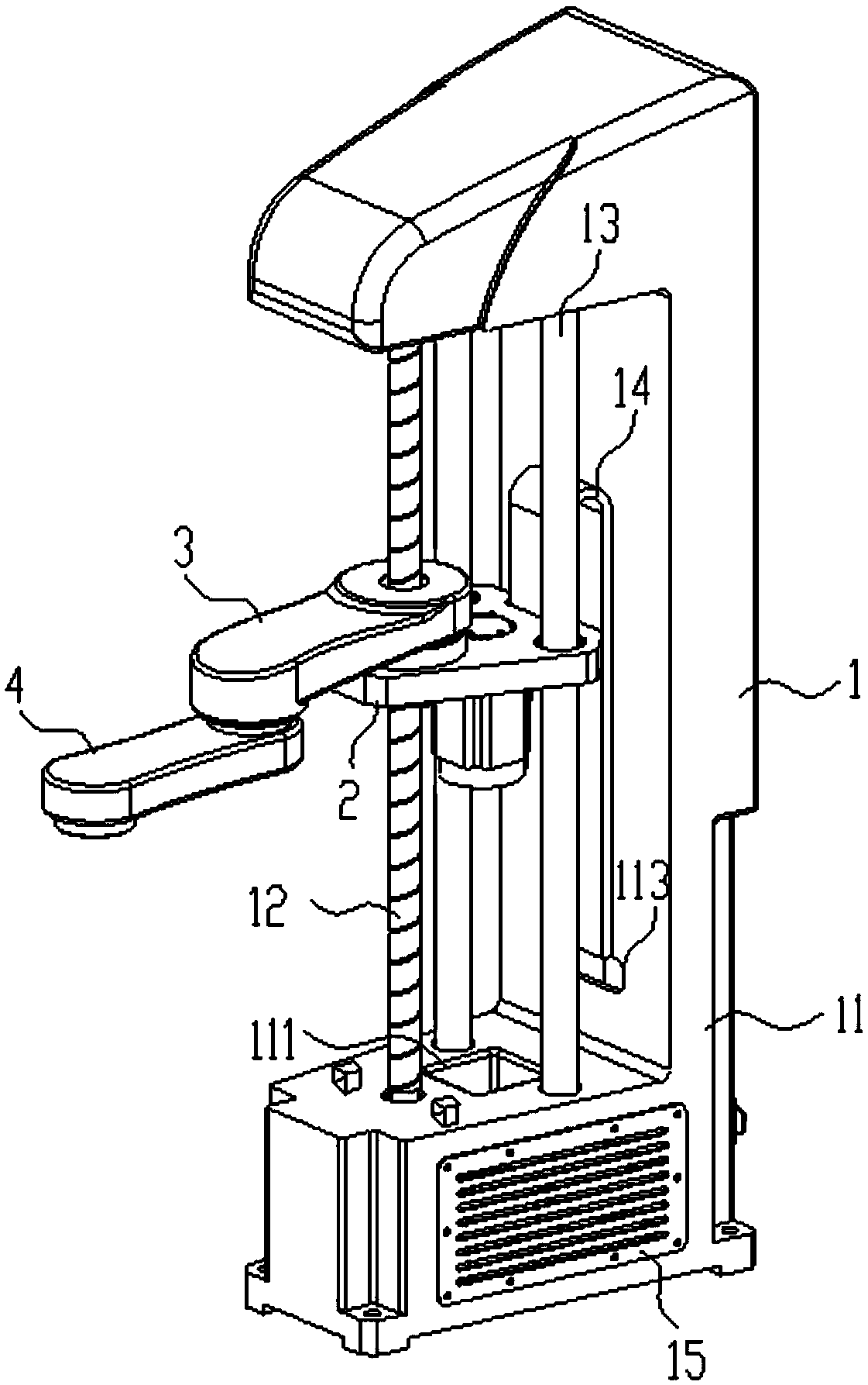
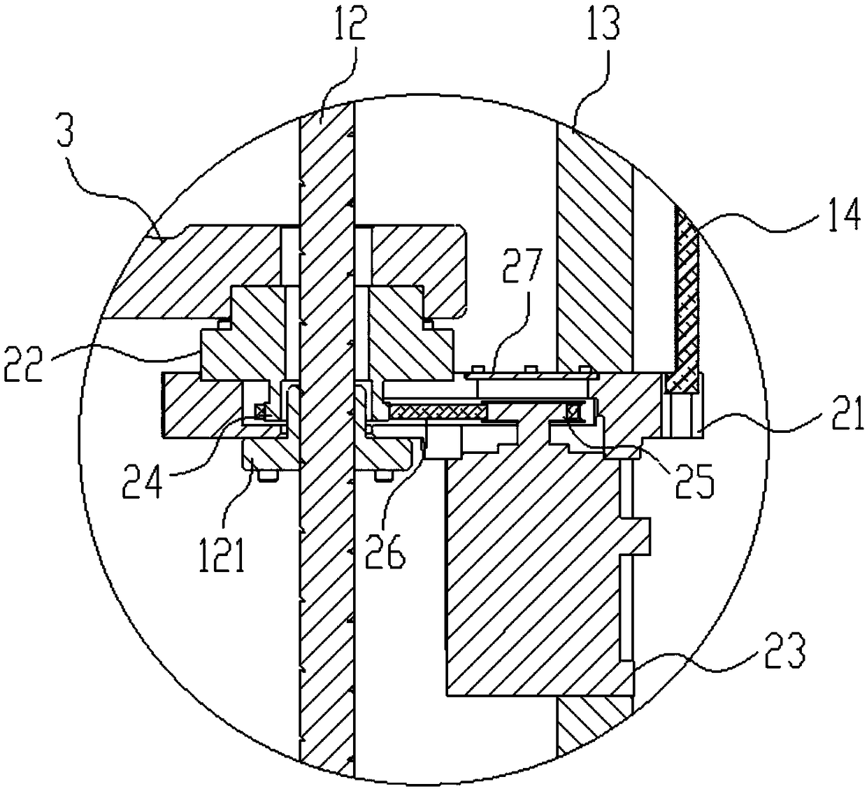
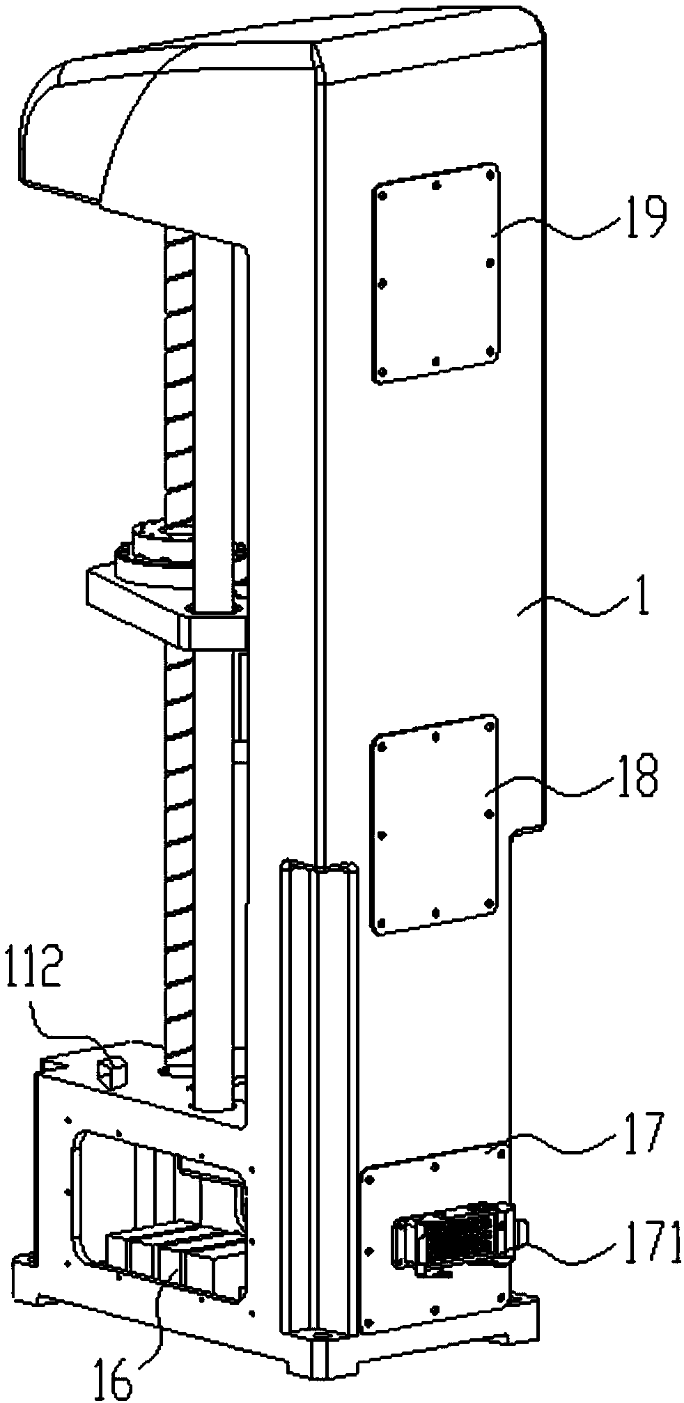
[0025] Such as Figure 1 to Figure 4 As shown, a four-joint planar robot includes a first joint part 1, a second joint part 2 installed in the first joint part 1 for linear motion up and down, and a third joint part 3 installed on the upper end of the second joint part 2 . The fourth joint part 4 installed at the lower end of the third joint part 3, the first joint part 1 includes a base 11, the front end of the base 11 is provided with a ball screw 12, and the rear end is provided with symmetrically arranged auxiliary fixing columns 13. A plastic drag chain 14 is provided on the outer wall of the base 11, one end of the plastic drag chain 14 is fixed to the base 11 and the other end is fixed to the second joint part 2;

[0026] The second joint part 2 includes a lifting base 21, a hol...


PUM


Abstract

The invention discloses a four-joint plane robot. The four-joint plane robot comprises a first joint part, a second joint part, a third joint part and a fourth joint part, the first joint part comprises a base, a ball screw is arranged at the front end of the base, the rear end of the base is provided with auxiliary fixing columns which are symmetrically arranged, and a plastic drag chain is arranged on the outer wall of the base; and the second joint part comprises a lifting seat, a hollow speed reducer and a motor, wherein one end of the lifting seat penetrates through the ball screw and isarranged at a lead screw nut of the ball screw, the other end of the lifting seat penetrates through the auxiliary fixing columns, an output belt wheel is installed on the hollow speed reducer, an input belt wheel is installed on the motor, the output belt wheel and the input belt wheel transmit torque through a synchronous belt, and a sealing cover plate is arranged on the lifting seat. Accordingto the four-joint plane robot, by utilizing the position and structure relationships between the ball screw and the auxiliary fixing columns, the up-and-down linear motion of the robot and the improvement on the motion rigidity are achieved, the third joint part can rotate around the axis of the ball screw, the movement range of the robot is effectively enlarged, and the rotational inertia is reduced.

Description

technical field [0001] The invention relates to the technical field of robot equipment, in particular to a four-joint planar robot. Background technique [0002] The up and down movement axis of the traditional SCARA robot is arranged at the end, and its working area is a fan-shaped surface. Because the volume of the end is relatively large, it is only suitable for the plane grabbing work in a large space. In addition, the rising distance of the end grab is limited by the height of the base. It is suitable for Up and down movements in a small range. [0003] Aiming at the shortcomings of the configuration of the transmission SCARA robot, the invention patent with the Chinese patent application number CN201710380194.6 discloses an upgraded drive mechanism and a planar joint robot, which changes the linear motion of the end of the SCARA to the linear up and down motion of the first axis of the robot, expanding the The range of motion, in order to maintain the overall rigidity...

Claims


Application Information

Patent Timeline
Patent Type & Authority Applications(China)
IPC IPC(8): B25J9/06
CPCB25J9/06
Inventor 刘凯章林开亚骏肖永强张帷俞和平
Owner EFORT INTELLIGENT EQUIP CO LTD
Why Eureka
Try Eureka