Prefabricated beam and construction method thereof

A construction method and technology of prefabricated beams, applied in the direction of manufacturing tools, joists, girders, etc., can solve difficulties and other problems, and achieve the effect of high structural strength

Active Publication Date: 2019-02-01
南通龙哲混凝土制品有限公司
View PDF7 Cites 1 Cited by
  • Summary
  • Abstract
  • Description
  • Claims
  • Application Information

AI Technical Summary

Problems solved by technology

[0003] At present, in order to facilitate the construction, the beams are generally prefabricated. During the construction, the beams are pulled over to build the shape, so as to complete the installation of the beams. In this process, there is no need to build molds in real time to pour the b

Method used


Image

  • Prefabricated beam and construction method thereof
  • Prefabricated beam and construction method thereof
  • Prefabricated beam and construction method thereof

Examples


Embodiment 1

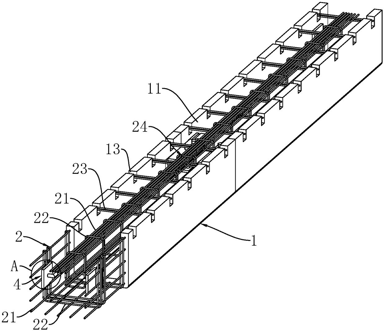
[0046] The utility model relates to a prefabricated beam, which is mainly used in building construction to bear the weight of the building and to form it. Such as figure 1 and figure 2 As shown, the prefabricated beam includes a beam body 1 with a U-shaped structure and prefabricated ribs 2 poured inside the beam body 1, so that the opening of the U-shaped beam body 1 faces upwards. At this time, when the beam body 1 is in use, place it It is transported to the location where it needs to be built, and after it is fixed in place, it is poured again inside the U-shaped structure to form a complete structural beam. In this process, the structural beam is formed by recasting the prefabricated beam as a template. On the one hand, it is lighter during transportation, and on the other hand, prefabricated ribs 2 can be added during recasting to improve its strength.

[0047] In the actual use process, the length of the beam can not be prefabricated too long in many cases, too long ...

Embodiment 2

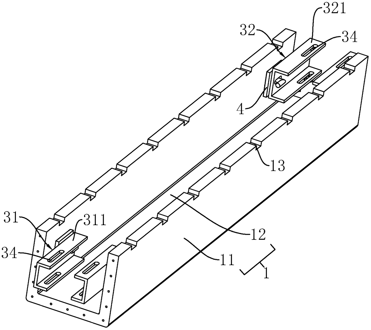
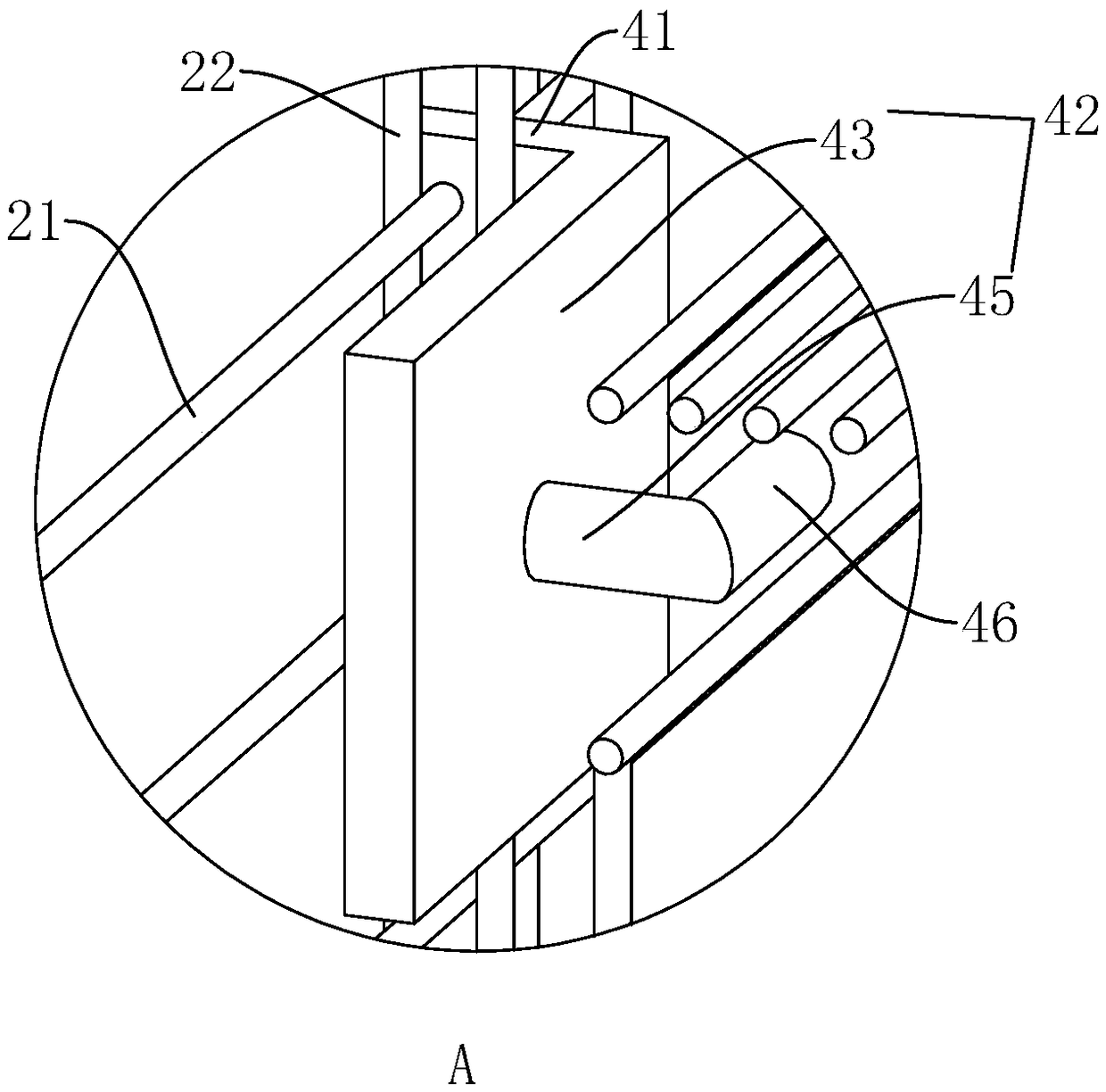
[0051] A kind of prefabricated beam, its basic structure is the same as that of Embodiment 1, the difference lies in the setting of connecting assembly 3, beam body 1 includes side wall 11 and bottom plate 12, side wall 11 is connected through connecting assembly 3 in embodiment 1, refer to Figure 4 and Figure 5 , That is, it is connected through the first connecting plate 31 , the second connecting plate 32 , the fixing piece 33 and the connecting piece 4 on the side wall 11 . And the connection hole 121 is set on the bottom plate 12, as Figure 6 As shown, the connection holes 121 are located at both ends of the beam body 1, and the inner connection plate 35 and the outer connection plate 36 are arranged between the connection holes 121 of the adjacent beam bodies 1, and the beams are connected by the inner connection plate 35 and the outer connection plate 36. The bottom plate 12 of the body 1 is clamped, and the locking piece 37 is passed between the inner connecting pl...

Embodiment 3

[0053] A prefabricated beam such as Figure 8 and Figure 9 As shown, including the beam body 1, the beam body 1 is a U-shaped structure, and the opening is upward, and the upper hook body 14 and the lower hook body 15 are respectively arranged on both sides of the beam body 1, and the upper hook body 14 and the lower hook body 15 As the two beam bodies 1 can be connected, it can be used as the connection assembly 3 on both sides of the beam body 1, and the upper hook body 14 and the lower hook body 15 can cooperate with each other, so that the sides of the beam body 1 can be combined to make the prefabricated beam body It can be tiled to increase the bearing capacity. Embodiment 3 can be used in conjunction with Embodiment 1 or Embodiment 2.


PUM


Abstract

The invention relates to the technical field of buildings, and discloses a prefabricated beam. The prefabricated beam comprises beam bodies each of a [-shaped structure and prefabricated ribs arrangedin the beam bodies in a penetrating mode; and the prefabricated ribs comprise strip-shaped ribs and stirrups, the strip-shaped ribs are arranged in the beam bodies, connecting pieces are arranged atthe ends of the beam bodies, connecting assemblies are arranged between adjacent beam bodies, and the connecting assemblies are fixedly connected with the connecting pieces correspondingly. The beam bodies of the [-shaped structures are light and thus are convenient to transport; through the prefabricated ribs, the beam bodies are firm, thus the beam bodies have the structures of initial beams, after construction, the beam bodies can be filled, and the internal structures of the beam bodies can be improved; in addition, the adjacent beam bodies are connected through the connecting assemblies,thus during using, the beam bodies can be connected through the connecting assemblies to form a whole, and integrality of the beam bodies is improved; and during construction, firstly, the beam bodiesare carried to the designated position, then grouting is conducted in the beam bodies of the [-shaped structures, and thus the complete structural beam is formed.

Description

technical field [0001] The invention relates to the technical field of construction, more specifically, it relates to a prefabricated beam and a construction method thereof. Background technique [0002] Beams are mainly subjected to lateral forces and shear forces, and bending is the main deformation component. The beam supports the entire weight of the components in the upper frame of the building and the roof, and is the most important part of the upper frame of the building. There are different names depending on the specific position, detailed shape, and specific functions of the beam. Most of the beams are oriented in line with the cross-section of the building. [0003] At present, in order to facilitate the construction, the beams are generally prefabricated. During the construction, the beams are pulled over to build the shape, so as to complete the installation of the beams. In this process, there is no need to build molds in real time to pour the beams, and it i...

Claims


Application Information

Patent Timeline
IPC IPC(8): E04C3/20E04G21/00B28B1/14B28B7/00B28B23/02
CPCB28B1/14B28B7/0029B28B23/02E04C3/20E04G21/00
Inventor 胡刚王冬华朱鑫鑫
Owner 南通龙哲混凝土制品有限公司
Why Eureka
Try Eureka