Rotary positioning and orientation equipment

A positioning, directional, and rotary technology, applied in mechanical equipment, transmission parts, gear transmissions, etc., can solve the problem of excessive axial movement positioning accuracy, and achieve the effect of avoiding parts wear and ensuring coaxiality.

Pending Publication Date: 2019-02-01
HUNAN AEROSPACE ELECTROMECHANICAL EQUIP & SPECIAL MATERIAL INST
View PDF0 Cites 0 Cited by
  • Summary
  • Abstract
  • Description
  • Claims
  • Application Information

AI Technical Summary

Problems solved by technology

This connection method is applied to rotary positioning and orientation equipment. Although the product can be driven normally, it will cause t

Method used


Image

  • Rotary positioning and orientation equipment
  • Rotary positioning and orientation equipment
  • Rotary positioning and orientation equipment

Examples


Example Embodiment

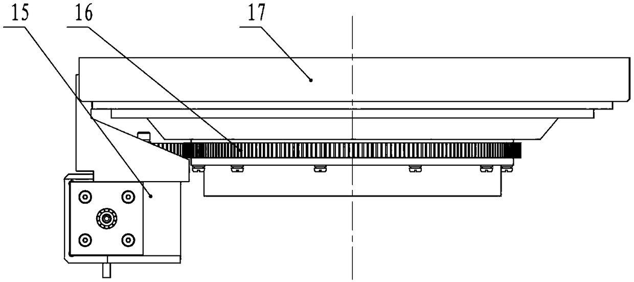
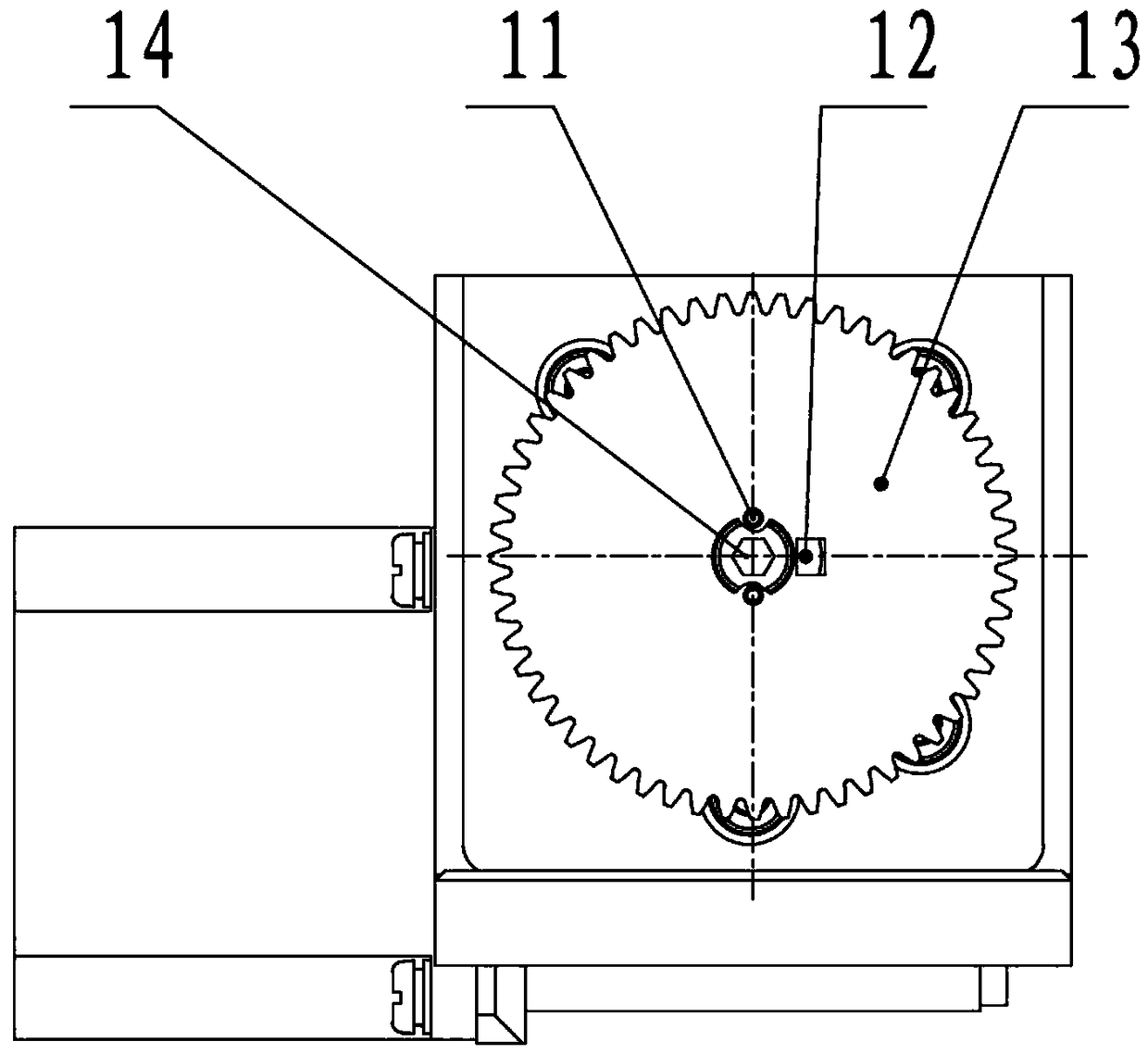
[0014] like figure 1 , figure 2 As shown, a kind of rotary positioning and orientation equipment includes a reducer 15, a rotating mechanism 17, a large gear 16 fixedly connected with the rotating mechanism 17, a pinion 13 driven by the reducer 15 and meshed with the large gear 16, and the reducer 15 is installed on one side of rotating mechanism 17.

[0015] Due to different space design requirements, the present invention proposes a driving scheme of using a worm gear reducer, and the problem of space utilization is effectively solved by installing the reducer on the side. Utilizing the characteristics of large transmission ratio of worm gear transmission, the transmission ratio is increased through two-stage reduction transmission, and a higher driving torque is obtained.

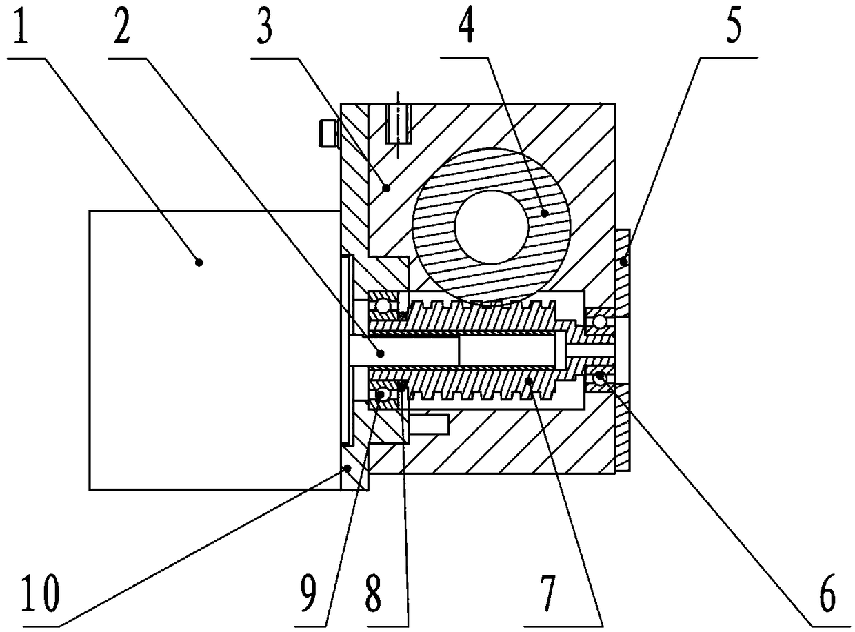
[0016] like image 3 As shown, the reducer includes a stepper motor 1 and a reducer housing 3, the reducer housing 3 is provided with a worm gear 4 and a worm 7 for meshing transmission, the output s...


PUM


Abstract

The invention relates to rotary positioning and orientation equipment. The rotary positioning and orientation equipment comprises a speed reducer, a rotating mechanism, a large gear which is fixedly connected with the rotating mechanism and a pinion which is driven by the speed reducer and is in meshed transmission with the large gear, the speed reducer is installed on one side of the rotating mechanism, the speed reducer comprises a stepping motor and a speed reducer shell, a worm wheel and a worm which are in meshed transmission are arranged in the speed reducer shell, an output shaft of thestepping motor penetrates into the worm, the pinion is fixedly connected with a worm wheel shaft, the end, close to the stepping motor, of the worm is provided with a first bearing, the other end ofthe worm is provided with a second bearing, and one side of the second bearing is provided with a bearing end cover. According to the rotary positioning and orientation equipment, on the basis of thecharacteristics of the rotary positioning and orientation equipment, a novel motor-bearing-bearing three-point type fixed assembly structure is designed different from a traditional worm gear reducerscheme, and the problem that due to the fact that an elastic wave washer is adopted in the axial direction of the stepping motor, the axial movement positioning precision of the rotating structure isextremely poor in a state of stopping rotation under a vibration working condition is solved.

Description

technical field [0001] The invention relates to a rotary positioning and orientation device. Background technique [0002] Rotary positioning and orientation equipment has the characteristics of high precision and needs to have an indexing mechanism. The indexing mechanism has the function that the driving mechanism can drive the rotating structure to continuously rotate around the rotating shaft. Due to the requirements of the operating environment, the positioning and orientation equipment usually needs to be evaluated under strict vibration, shock, overload, and wide operating temperature range. The positioning and orientation equipment needs to be used in a low temperature environment of -40°C. There are strict requirements on the positioning accuracy of the axial movement of the rotating structure. Therefore, in the field of drive design of rotary positioning and orientation equipment, drive design is a key technology. The indexing mechanism with driving mechanism in...

Claims


Application Information

Patent Timeline
IPC IPC(8): F16H1/20F16H57/023F16H57/039
CPCF16H1/203F16H57/023F16H57/039
Inventor 李丹萍刘忠
Owner HUNAN AEROSPACE ELECTROMECHANICAL EQUIP & SPECIAL MATERIAL INST
Why Eureka
Try Eureka