
Antenna alignment method and device

A technology for aligning devices and antennas, applied in antennas, wireless communications, services based on location information, etc., can solve the problems of inconsistency in gain, the inconsistency of antennas to meet its requirements, inconsistency in phase and delay, and achieve improved omnidirectionality. performance, improve communication quality, and high positioning accuracy

Inactive Publication Date: 2019-02-01
BEIJING BOOCAX TECH CO LTD
View PDF6 Cites 6 Cited by
  • Summary
  • Abstract
  • Description
  • Claims
  • Application Information

AI Technical Summary

Problems solved by technology

Under ideal conditions, UWB positioning technology can achieve extremely high accuracy. However, due to the inconsistency of antenna performance in all directions, such as inconsistency in gain, inconsistency in phase and delay, the accuracy of UWB positioning is seriously affected.
UWB positioning technology has extremely high requirements for the consistency of antenna performance in all directions, and it is difficult for UWB antennas on the market to meet its requirements

Method used


Image

  • Antenna alignment method and device
  • Antenna alignment method and device
  • Antenna alignment method and device

Examples


Embodiment Construction

[0049] The implementation of the present invention will be described in detail below in conjunction with the accompanying drawings and examples, so as to fully understand and implement the process of how to apply technical means to solve technical problems and achieve technical effects in the present invention. It should be noted that, as long as there is no conflict, each embodiment and each feature in each embodiment of the present invention can be combined with each other, and the formed technical solutions are all within the protection scope of the present invention.

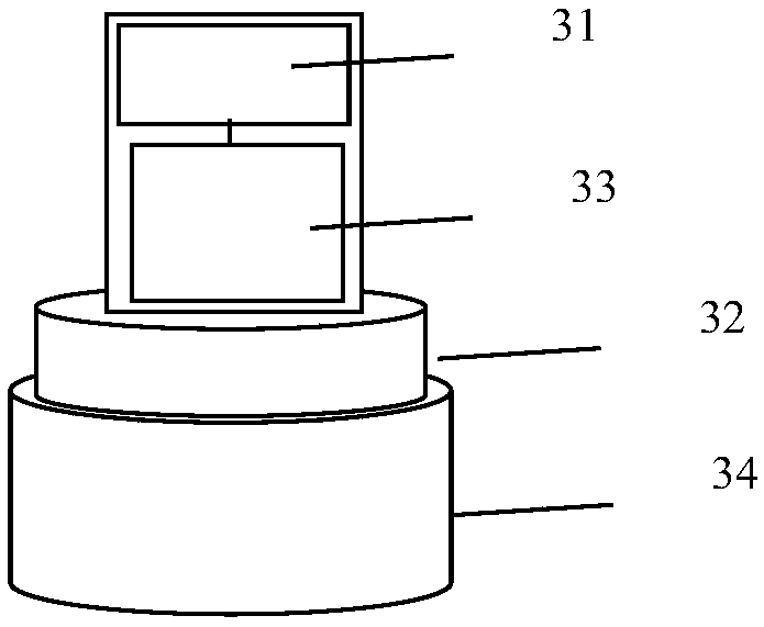
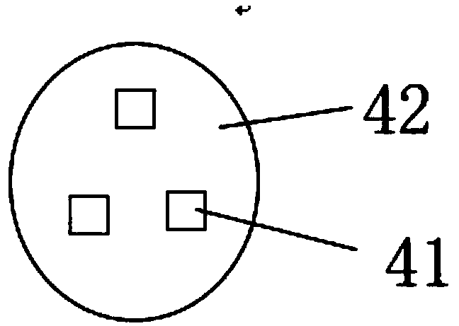
[0050] Such as Figure 1-4As shown, the present disclosure provides an antenna alignment method and device, the device includes a user end device and a base station end device; the user end device includes a wireless transmitter or transceiver and a control unit; the base station end device includes a wireless The receiver or transceiver also includes a group of antenna arrays, and a motor that can control t...


PUM


Abstract

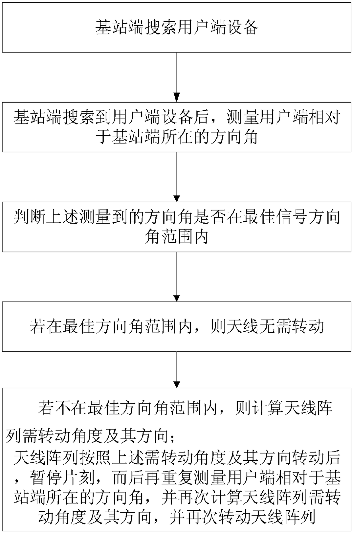
The invention discloses an antenna alignment method and device. The method comprises the steps of: searching user side equipment by a base station side; after the base station side searches out the user side equipment, measuring a direction angle at which a user side is positioned relative to the base station side; judging whether the measured direction angle is within an optimal signal directionangle range; if the measured direction angle is within the optimal direction angle range, not rotating an antenna; if the measured direction angle is not within the optimal direction angle range, calculating a demanded rotating angle of an antenna array and a direction thereof; and after the antenna array rotates according to the demanded rotating angle of the antenna array and the direction thereof, pausing a while, then repeatedly measuring a direction angle at which the user side is positioned relative to the base station side, calculating the demanded rotating angle of the antenna array and the direction thereof again, and rotating the antenna array again.

Description

technical field [0001] The present invention belongs to the field of antenna technology disclosed herein, and in particular relates to an antenna alignment method and device. Background technique [0002] Antenna is the front-end device of wireless communication, but even if it is an omnidirectional antenna, its performance in all directions is difficult to achieve consistency. In the case where both the receiving and transmitting ends are in a static state, the installation direction of the antenna can be manually adjusted so that the best signal direction of the antenna is aligned with the communication target. However, in the case where the relative position of the transceiver often changes, the artificial adjustment method is no longer available. [0003] Ultra-wideband technology (UWB) has the advantages of low power consumption, strong anti-interference ability, strong anti-multipath effect ability, etc., and has been widely used in indoor positioning. Under ideal co...

Claims


Application Information

Patent Timeline
IPC IPC(8): H04B17/21H04B17/11H04W4/02H04W64/00H01Q3/02G05D3/12
CPCG05D3/12H01Q3/02H04B17/11H04B17/21H04W4/02H04W64/00
Inventor 张东泉谢传泉浦剑涛
Owner BEIJING BOOCAX TECH CO LTD
Learn More