A Fast Automatic Exposure Graphics Generation Method
A technology of automatic exposure and graphics, which is used in the control of exposure, optics, image communication, etc., and can solve the problem of high time complexity of automatic exposure of display panels
- Summary
- Abstract
- Description
- Claims
- Application Information
AI Technical Summary
Problems solved by technology
Method used
Image
Examples
Embodiment 1
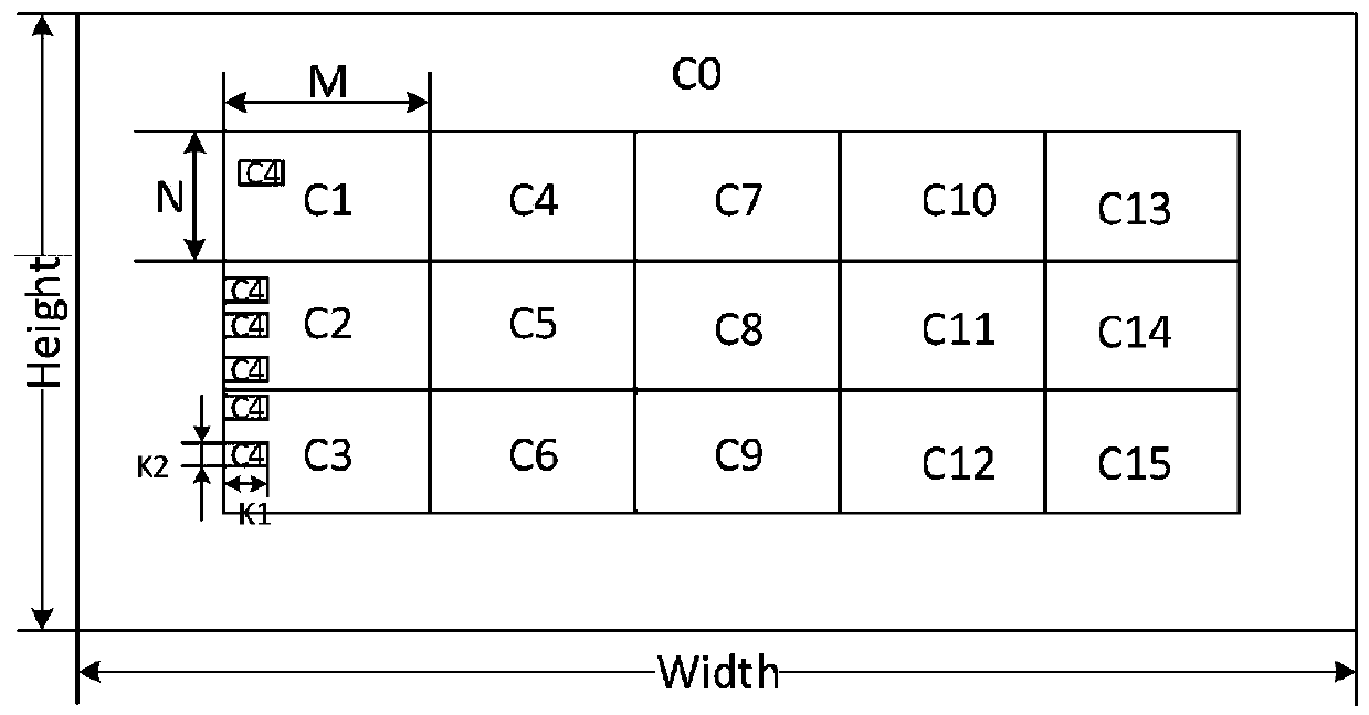
[0031] Embodiment 1 provides a fast automatic exposure pattern, such as figure 1 As shown, it includes: a graphic area; a first limited area is formed in the graphic area, the first limited area is located at the center of the graphic area, and the resolution of the first limited area is Width*Height.
[0032] Within the graphics area, the area outside the first defined area is defined as an unrestricted area; the unrestricted area is filled with a first contrasting color, and the first contrasting color can be L0, i.e. RGB (0, 0,0).
[0033] A plurality of tiles are formed in the first limited area, each tile has a resolution of M*N, and the plurality of tiles include four feature tiles and at least three grayscale tiles. Wherein, the four characteristic blocks are respectively recorded as a first characteristic block, a second characteristic block, a third characteristic block, and a fourth characteristic block.
[0034] The first feature block includes i identification bl...
Embodiment 2
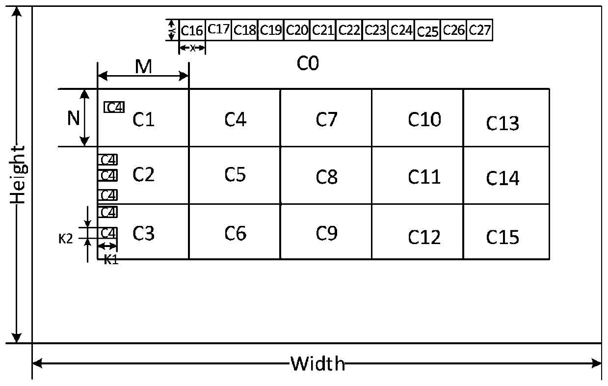
[0039] Embodiment 2 provides a fast automatic exposure pattern in the case of uneven brightness of the display panel, such as figure 2 As shown, the second limited area is added on the basis of Example 1.
[0040] The second limited area is formed in the graphics area, and the second limited area includes a plurality of sub-blocks, each of which has a resolution of X*Y, and different sub-blocks are filled with different grays. step color.
[0041] The second limited area is suggested to be placed at the edge of the graphic area, which is better applicable to the situation of uneven brightness at the edge of the display panel.
[0042]In embodiment 2, the area within the graphic area and outside the first limited area and the second limited area is defined as an undefined area; the undefined area is filled with a first contrasting color, so The first contrast color can be L0, ie RGB(0,0,0).
[0043] That is, Embodiment 2 designs a pattern image of multiple sub-blocks, which...
Embodiment 3
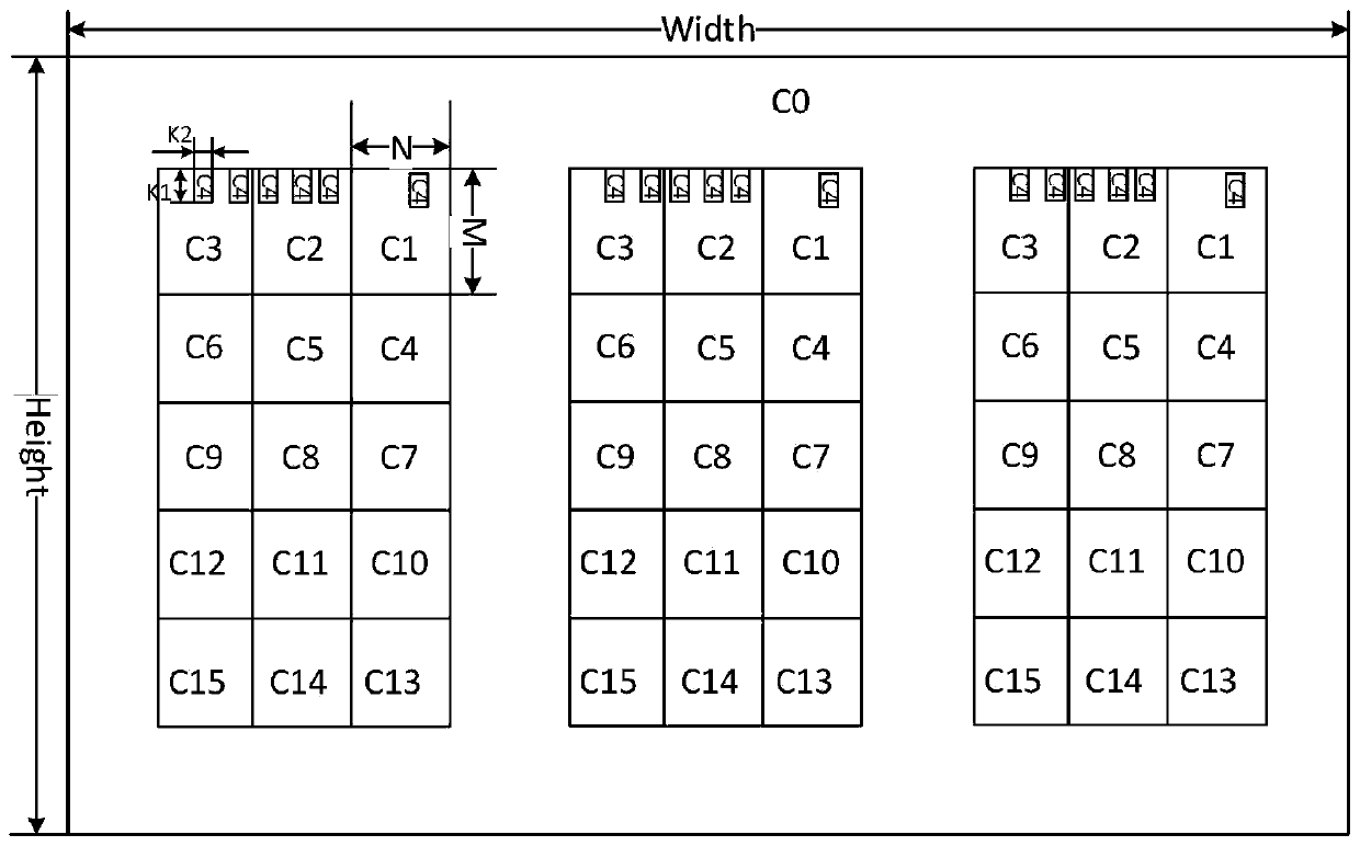
[0045] Embodiment 3 provides a fast auto-exposure graphic in the case of multi-camera shooting, such as image 3 As shown, there are multiple first limited areas, and each of the first limited areas is used to correspond to a camera.
[0046] That is, if multiple cameras capture the pattern picture of the display panel, the area under each camera needs to make a graphic pattern according to the method of embodiment 1.
[0047] To sum up, embodiment 1 is mostly used when the brightness of the display panel is relatively uniform, embodiment 2 is mostly used when the brightness of the edge of the display panel is uneven, and embodiment 3 is used for multi-camera shooting.
[0048] The contrast effect of image brightness before camera exposure, iterative automatic exposure, and fast automatic exposure, as shown in Table 1:
[0049] Table 1 Comparison of automatic exposure effects of different methods
[0050]
[0051] Iterative camera auto-exposure and fast auto-exposure time...
PUM
 Abstract
Description
Claims
Application Information
 - R&D
- Intellectual Property
- Life Sciences
- Materials
- Tech Scout
- Unparalleled Data Quality
- Higher Quality Content
- 60% Fewer Hallucinations
Browse by: Latest US Patents, China's latest patents, Technical Efficacy Thesaurus, Application Domain, Technology Topic, Popular Technical Reports.
© 2025 PatSnap. All rights reserved.Legal|Privacy policy|Modern Slavery Act Transparency Statement|Sitemap|About US| Contact US: help@patsnap.com


