
Indoor positioning and mapping method based on depth camera and thermal imager

A technology of depth camera and indoor positioning, applied in 2D image generation, instruments, image enhancement and other directions, can solve the problems of large amount of calculation, high cost, low applicability, etc., and achieve the effect of improving accuracy, accurate positioning, and stable imaging

Active Publication Date: 2020-12-01
HEBEI UNIV OF TECH
View PDF3 Cites 3 Cited by
  • Summary
  • Abstract
  • Description
  • Claims
  • Application Information

AI Technical Summary

Problems solved by technology

However, in the actual use environment, walking people and pets are dynamic objects. When such features are extracted for pose estimation, it will obviously cause serious positioning errors.
[0003] At present, although there are some methods to solve the dynamic SLAM problem, such as DS-SLAM, most of these methods are systems built based on deep learning neural networks and auxiliary algorithms; neural networks are used for target detection, thereby eliminating dynamic objects at the algorithm level features, the neural network uses color images to extract features, and there are cases of missing and false detections; and the auxiliary algorithm can compensate for the missed detections and false detections of the neural network, but this method is complex and requires a large amount of calculation. Only powerful GPU acceleration can realize real-time processing, which has high cost and low applicability

Method used


Image

  • Indoor positioning and mapping method based on depth camera and thermal imager
  • Indoor positioning and mapping method based on depth camera and thermal imager
  • Indoor positioning and mapping method based on depth camera and thermal imager

Examples


Embodiment Construction

[0036] The present invention will be further described below in conjunction with the accompanying drawings and specific embodiments.

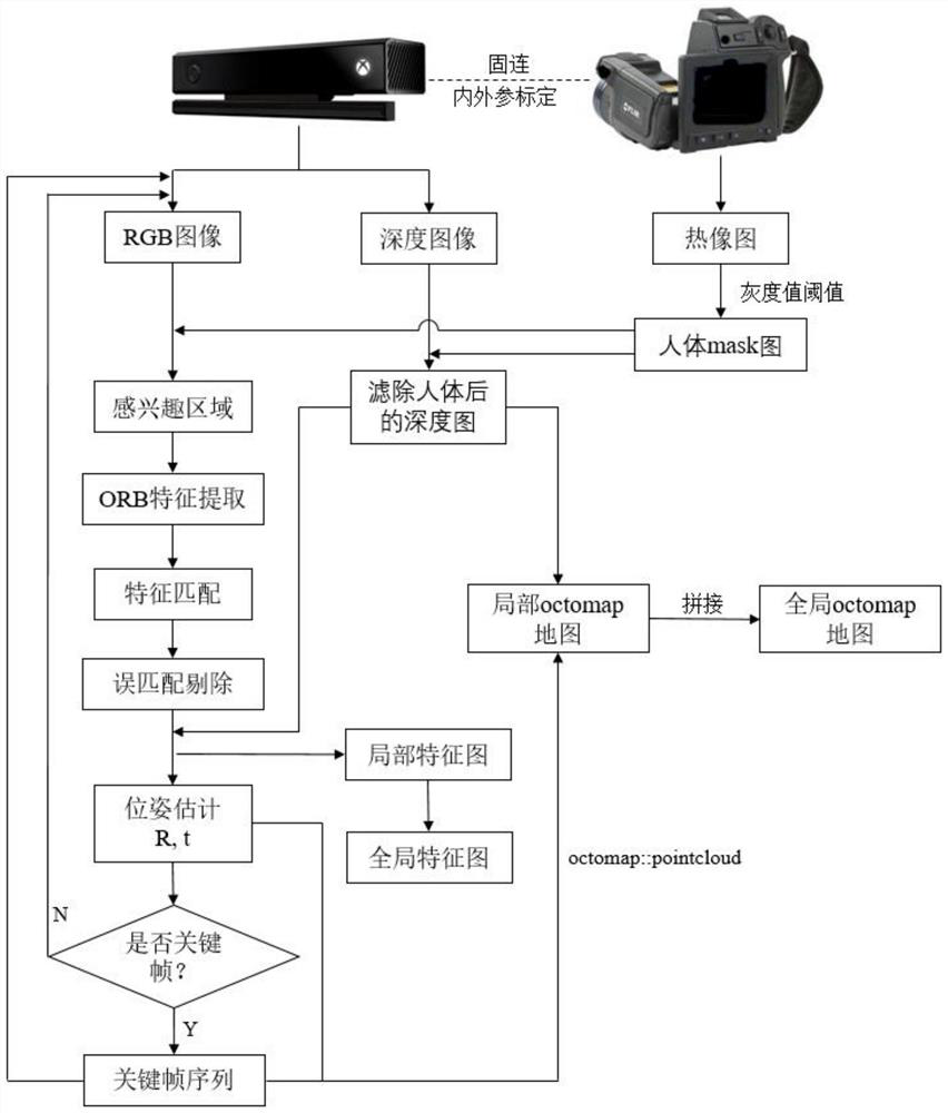
[0037] The present invention provides an indoor positioning and mapping method based on a depth camera and a thermal imager (method for short, see Figure 1-4 ), including the following steps:

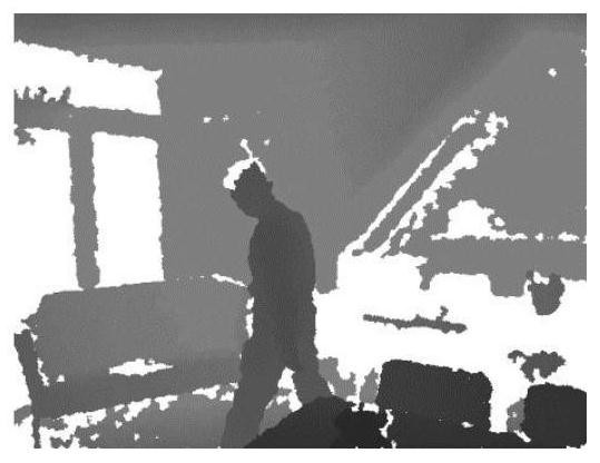
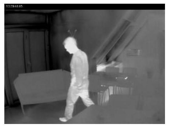
[0038] Step 1. First, fix the depth camera and thermal imager, so that the depth camera and thermal imager include most of the common field of view, and then fix the depth camera and thermal imager on the robot together; and carry out the depth camera and thermal imager Calibration of internal and external parameters enables pixel-by-pixel registration of RGB images, depth images and thermal images in the same field of view;

[0039] The depth camera (model is Kinect v2) is equipped with a color lens and a depth lens, which can obtain the color image and depth image of the scene; the color image is used to obtain the color information of the scene and ...


PUM


Abstract

The invention discloses an indoor positioning and mapping method based on a depth camera and a thermal imager, and the method comprises the following steps: 1, enabling the depth camera and the thermal imager to be fixedly connected, and carrying out the internal and external parameter calibration of the depth camera and the thermal imager; 2, acquiring an image by using a depth camera and a thermal imager, and processing the thermal image according to a gray value threshold of a human body region to obtain a human body mask image; 3, fusing the RGB image with the corresponding human body maskimage to obtain a region of interest of the RGB image; constructing a pose relationship between adjacent frames of images, and iteratively solving the pose relationship through a nonlinear optimization algorithm to obtain the pose of the color lens; and 4, extracting a key frame image, sending the depth image and the human body mask image corresponding to the key frame image into a mapping thread, and constructing a global Octomap. According to the method, the dynamic characteristics are extracted by fully utilizing the characteristic that the thermal imager senses the temperature, so that the dynamic characteristics can be effectively avoided during mapping, and the positioning and mapping precision is improved.

Description

technical field [0001] The invention belongs to the technical field of robot intelligent perception and environment modeling, and specifically relates to an indoor positioning and mapping method based on a depth camera and a thermal imager. Background technique [0002] At present, service robots have not been mass-produced and widely used. An important factor restricting their development is the robust localization and mapping (SLAM) method. The existing SLAM methods are all based on the basic assumption of static scenes, that is, it is assumed that the space in which the robot is located is static, so the extracted features are all static, and these features are used for environment modeling and robot pose estimation. However, in the actual use environment, walking people and pets are dynamic objects. When such features are extracted for pose estimation, it will obviously cause serious positioning errors. [0003] At present, although there are some methods to solve the d...

Claims


Application Information

Patent Timeline
Patent Type & Authority Applications(China)
IPC IPC(8): G06T11/20G06T7/73G06T7/11G06T7/80G06T5/50G06T7/00G01C11/02G01C21/20
CPCG06T11/206G06T7/73G06T7/11G06T7/80G06T5/50G06T7/97G01C11/02G01C21/206G06T2207/30196G06T2207/20221G06T2207/10028Y02T10/40
Inventor 张建华张霖赵岩李辉
Owner HEBEI UNIV OF TECH
Learn More