Laser engraving machine and engraving method

A laser engraving machine and fuselage technology, applied in the engraving field, can solve the problems of increased cost, insufficient product refinement, low efficiency, etc., and achieve the effect of reducing production cost and diversifying production.

Pending Publication Date: 2019-02-05
东莞市德懋机电有限公司
View PDF0 Cites 0 Cited by
  • Summary
  • Abstract
  • Description
  • Claims
  • Application Information

AI Technical Summary

Problems solved by technology

[0002] More and more products on the market need to print LOGO or other patterns. Traditionally, spraying or printing are used to complete the process. The production process efficiency of these processes is low, and the finished products are not refined enough;
[0003] In order to overcome the above shortcomings, laser engraving machines appear on the market, which can laser engrave or mark products through lasers. Laser engraving machines are a process that uses optical principles for surface treatment. The accuracy has been greatly improved, but the existing laser engraving machine is only equipped with a material carrier for a certain type of part, and can only laser engrave the specific part. The utilization rate of the laser engraving machine is low. For laser engraving, it is necessary to purchase different laser engraving machines, which will greatly increase the cost of the factory and is not suitable for diversified production

Method used


Image

  • Laser engraving machine and engraving method
  • Laser engraving machine and engraving method
  • Laser engraving machine and engraving method

Examples


Embodiment Construction

[0029] In order to facilitate the understanding of those skilled in the art, the present invention will be further described below in conjunction with the embodiments and accompanying drawings, and the content mentioned in the implementation mode is not to limit the present invention. The present invention is described in detail below in conjunction with accompanying drawing.

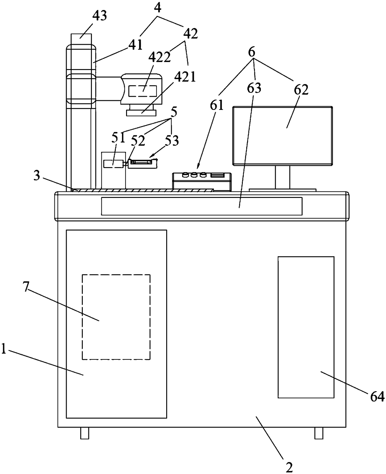
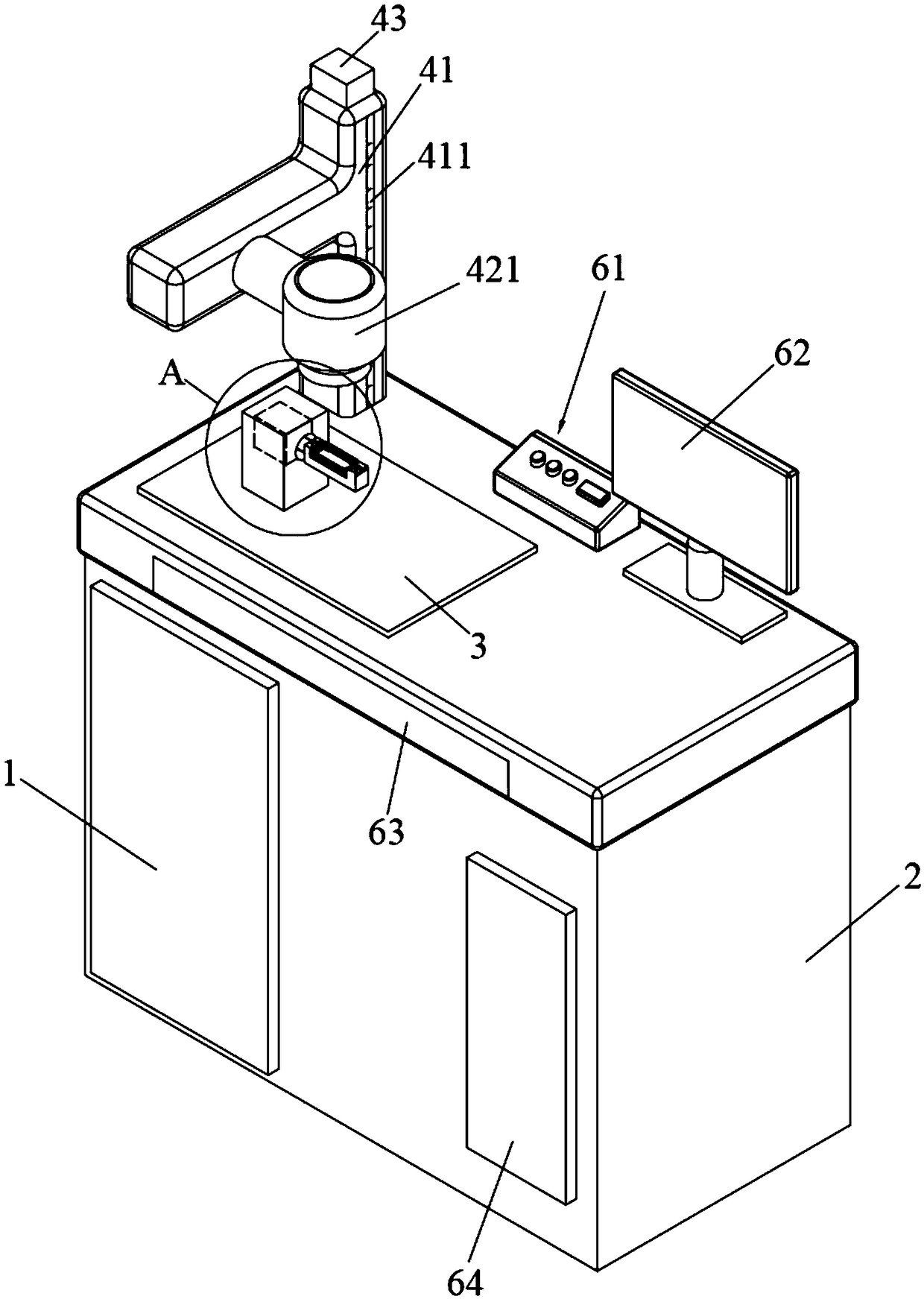
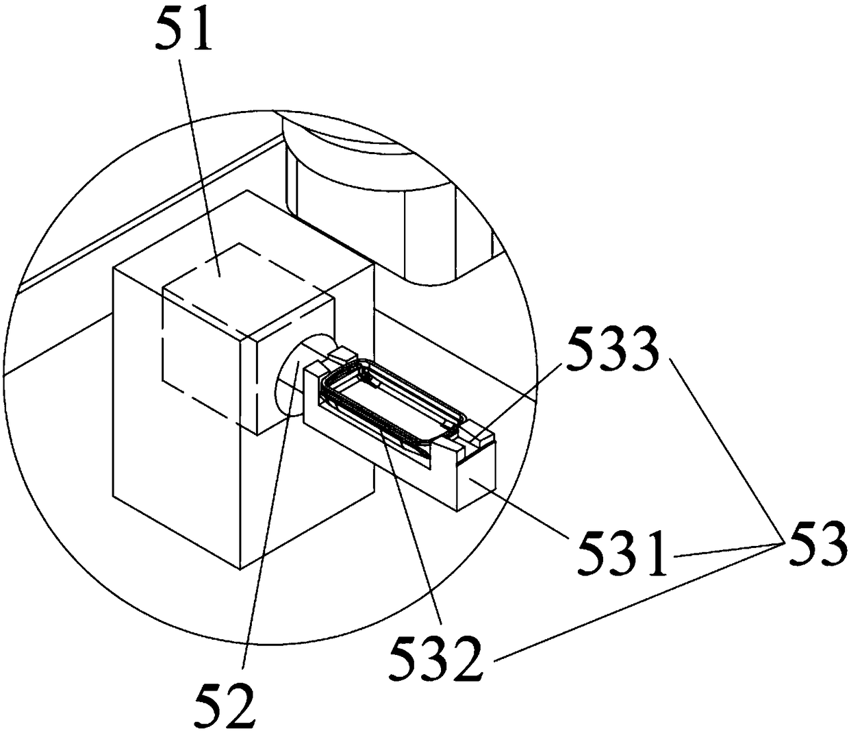
[0030] A kind of laser engraving machine provided in this embodiment, such as figure 1 , including a control box 1, a fuselage 2 and a workbench 3 arranged on the fuselage 2, the fuselage 2 is provided with an engraving device 4 for engraving products, and a rotating device 5 is provided below the engraving device 4, so Both the engraving device 4 and the rotating device 5 are electrically connected to the control box 1, the rotating device 5 includes a first driving mechanism 51, a rotating shaft 52 and a clamping mechanism 53 for fixing the product, the first driving mechanism 51 is set On the workta...


PUM


Abstract

The invention relates to the technical field of engraving, in particular to a laser engraving machine and an engraving method. The laser engraving machine comprises a control cabinet, a machine body and a working table arranged on the machine body. An engraving device used for engraving a product is arranged on the machine body. A rotating device is arranged below the engraving device. The engraving device and the rotating device are both electrically connected with the control cabinet. The rotating device comprises a first driving mechanism, a rotary shaft and a clamping mechanism used for fixing the product. The first driving mechanism is arranged on the working table. One end of the rotary shaft is connected with the first driving mechanism, and the other end of the rotary shaft is connected with the clamping mechanism. The laser engraving machine provided by the invention is provided with the clamping mechanism capable of flexibly adjusting and changing the product, and the position of the laser engraving machine during operation can be flexibly adjusted and changed. The laser engraving machine is suitable for engraving of various types of products, achieves the purpose of production diversification and reduces the production cost of a factory.

Description

technical field [0001] The invention relates to the technical field of engraving, in particular to a radium engraving machine and an engraving method. Background technique [0002] More and more products on the market need to print LOGO or other patterns. Traditionally, spraying or printing are used to complete the process. The production process efficiency of these processes is low, and the finished products are not refined enough; [0003] In order to overcome the above shortcomings, laser engraving machines appear on the market, which can laser engrave or mark products through lasers. Laser engraving machines are a process that uses optical principles for surface treatment. The accuracy has been greatly improved, but the existing laser engraving machine is only equipped with a material carrier for a certain type of part, and can only laser engrave the specific part. The utilization rate of the laser engraving machine is low. For laser engraving, it is necessary to purcha...

Claims


Application Information

Patent Timeline
Patent Type & Authority Applications(China)
IPC IPC(8): B23K26/362B23K26/70
CPCB23K26/361B23K26/362B23K26/70B23K26/702
Inventor 张礼明
Owner 东莞市德懋机电有限公司
Why Eureka
Try Eureka