Calibrating method and device of tool coordinate system as well as computer-readable storage medium

A tool coordinate system and calibration method technology, applied in the tool coordinate system calibration method, computer-readable storage media, and device fields, can solve the problems of time-consuming, laborious, high cost, etc., achieve reduced requirements, simplify the calibration process and, The effect of reducing the amount of related error brought in

Active Publication Date: 2019-02-05
GREE ELECTRIC APPLIANCES INC
View PDF3 Cites 4 Cited by
  • Summary
  • Abstract
  • Description
  • Claims
  • Application Information

AI Technical Summary

Problems solved by technology

[0002] There are many kinds of tool coordinate system (TCS, Tool Coordinate System) calibration methods, including self-calibration methods and auxiliary calibration methods with other precision instruments, but these calibration methods are not only expensive, but also time-consuming and labor-intensive. For example, the commonly used With the six-point self-calibration algorithm, in addition to changing the specified number of teaching points for teaching in different postures of the robot before calibration, it is also necessary to calculate the TCP (Tool Center Point) pose of the tool coordinate system through complex calculations. There are requirements for the accuracy of the transmission mechanism of the robot body, and also for the control algorithm of the robot. These factors have a great influence on the final calibration accuracy of the robot. Therefore, it is necessary to provide a calibration method that can minimize related factors during the calibration process. influence, reducing the accumulation of calibration errors

Method used


Image

  • Calibrating method and device of tool coordinate system as well as computer-readable storage medium
  • Calibrating method and device of tool coordinate system as well as computer-readable storage medium
  • Calibrating method and device of tool coordinate system as well as computer-readable storage medium

Examples


Embodiment Construction

[0054] In order to make the purpose, technical solutions and advantages of the embodiments of this application clearer, the technical solutions in the embodiments of this application will be described clearly and completely in conjunction with the drawings in the embodiments of this application. Obviously, the described embodiments These are a part of the embodiments of this application, but not all of the embodiments. Based on the embodiments in this application, all other embodiments obtained by those of ordinary skill in the art without creative work shall fall within the protection scope of this application.

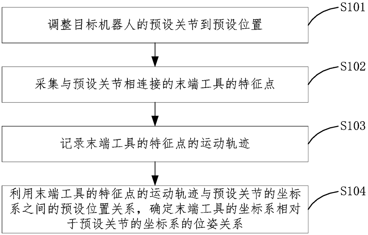
[0055] figure 1 A method for calibrating a tool coordinate system provided in an embodiment of this application is applied to an industrial robot. The calibration method includes the following steps:

[0056] S101. Adjust a preset joint of the target robot to a preset position.

[0057] S102: Collect feature points of the end tool connected to the preset joint.
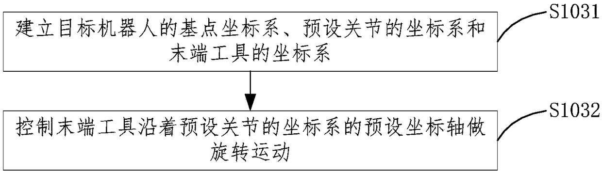
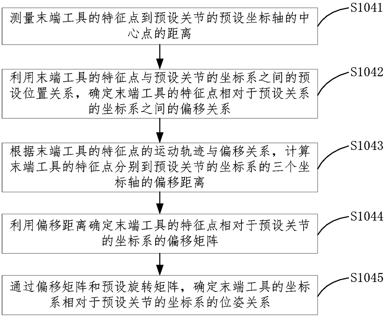
[0058] S10...


PUM


Abstract

The invention relates to a calibrating method and device of a tool coordinate system as well as a computer-readable storage medium. The calibrating method comprises the following steps: adjusting a preset joint of a target robot to a preset position; acquiring a feature point of an end-of-arm tooling connected with the preset joint; recording a motion trail of the feature point of the end-of-arm tooling; and determining the pose relation, of a coordinate system of the end-of-arm tooling, relative to a coordinate system of the preset joint, by using the preset position relation between the motion trail of the feature point of the end-of-arm tooling and the coordinate system of the preset joint. According to the technical schemes of the embodiments of the invention, neither changing of the posture of the target robot for many times nor complex calculation formulas are needed, the calibration process of the tool coordinate system and the calculation process of the calibration algorithm are simplified, the need of the calibration on calculation capacity is lowered, the calibration efficiency is improved, the number of introduced relevant error amounts is reduced, and the calibration precision is increased.

Description

Technical field [0001] This application relates to the field of machinery, and in particular to a method, device and computer-readable storage medium for calibrating a tool coordinate system. Background technique [0002] There are many types of tool coordinate system (TCS, Tool Coordinate System) calibration methods, including self-calibration methods and auxiliary calibration methods with the help of other precision instruments. However, these calibration methods are not only costly, but also time-consuming and labor-intensive in the calibration process, such as commonly used Six-point self-calibration algorithm. Before calibration, in addition to transforming the specified number of teaching points in different postures of the robot, it also needs to calculate the TCP (Tool Center Point) pose of the tool coordinate system through complex calculations. The accuracy of the robot body transmission mechanism is required, and there are also requirements for the robot control algori...

Claims


Application Information

Patent Timeline
Patent Type & Authority Applications(China)
IPC IPC(8): B25J9/16
CPCB25J9/1664B25J9/1697
Inventor 赵航刘新卫雷俊松刘旭魏佳欣邓绍熙胡飞鹏
Owner GREE ELECTRIC APPLIANCES INC
Why Eureka
Try Eureka