
Stacking machine, grabbing device and grabbing hook mechanisms

A grasping device and hook claw technology, which is applied in the stacking of objects, conveyor objects, destacking of objects, etc., can solve the problems of complex structure and large volume of the grasping device, and achieve simple structure, small volume, and economical efficiency. energy effect

Active Publication Date: 2019-02-05
YUNNAN ZHUOPEI TECH
View PDF5 Cites 4 Cited by
  • Summary
  • Abstract
  • Description
  • Claims
  • Application Information

AI Technical Summary

Problems solved by technology

[0002] At present, the goods in the cargo storage system are transported and stacked by stacking palletizers. The grabbing device of the stacking palletizer is composed of two grabbing hook mechanisms on the left and right. The grabbing hook mechanisms are generally driven by the following methods: through hydraulic cylinders or air pressure The cylinder drives the claws on the telescopic rod to move horizontally to form a space for placing the goods, so as to grab the goods for subsequent lifting and lateral movement. In this way, the structure of the whole grabbing device is complicated due to the existence of the hydraulic or pneumatic system. , bulky

Method used


Image

  • Stacking machine, grabbing device and grabbing hook mechanisms
  • Stacking machine, grabbing device and grabbing hook mechanisms
  • Stacking machine, grabbing device and grabbing hook mechanisms

Examples


Embodiment Construction

[0042] Embodiments of the present invention will be further described below in conjunction with the accompanying drawings.

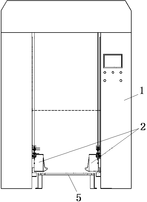
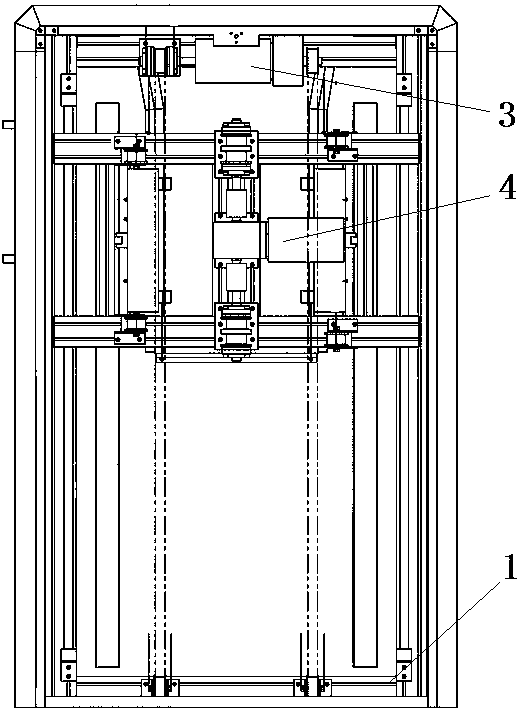
[0043] The specific embodiment of stacker of the present invention, as Figure 1 to Figure 5 As shown, the stacking palletizer includes a frame 1, and the outer periphery of the frame 1 has a sealing plate, which is located at the opposite sides of the stacking palletizer to reserve the entrance and exit of the goods, and the lower space between the entrance and the exit A guiding device 5 is arranged on the top, and the guiding device 5 has a guiding platform for placing the goods. Above the guiding device 5, on the frame 1 and inside the sealing plate, a grabbing device 2 for grabbing the goods is provided. On the frame 1, there is also a A lifting device 4 and a traverse device 3 for driving the grabbing device 2 and the goods it grabs to move are installed.

[0044] Grabbing device 2 comprises two grapple mechanisms 21 that are relatively symmetrica...


PUM


Abstract

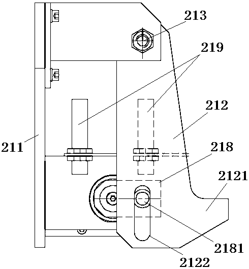
The invention relates to a stacking machine, a grabbing device and grabbing hook mechanisms. The stacking machine comprises a frame, a transverse moving device, a lifting device, a guide device and the grabbing device for grabbing goods. The grabbing device comprises the two oppositely arranged grabbing hook mechanisms. A space for accommodating the goods is formed between the two grabbing hook mechanisms. The grabbing hook mechanisms comprise mounting frames provided with hook claws. One ends of the hook claws are hinged to the mounting frames, and the other ends of the hook claws are provided with hooking parts for hooking the goods. The mounting frames are also provided with a motor. An output shaft of the motor is in transmission connection with a crank arm which drives the hook clawsto rotate around the hinge points of the mounting frames and the hook claws. The hook claws have hooking positions for hooking the goods and disengaging positions for disengaging the goods in the rotating process. The motor drives the crank arm to swing to drive the hook claws to rotate around hinge shafts of the hook claws so as to grasp the goods. Compared with the traditional way of driving thehook claws to move horizontally by a hydraulic cylinder and a pneumatic cylinder, the grabbing device is simple in structure, small in size and good in applicability.

Description

technical field [0001] The invention relates to a stacker, a grabbing device and a grabbing hook mechanism. Background technique [0002] At present, the goods in the cargo storage system are transported and stacked by stacking palletizers. The grabbing device of the stacking palletizer is composed of two grabbing hook mechanisms on the left and right. The grabbing hook mechanisms are generally driven by the following methods: through hydraulic cylinders or air pressure The cylinder drives the claws on the telescopic rod to move horizontally to form a space for placing the goods, so as to grab the goods for subsequent lifting and lateral movement. In this way, the structure of the whole grabbing device is complicated due to the existence of the hydraulic or pneumatic system. , bulky. Contents of the invention [0003] The purpose of the present invention is to provide a grapple mechanism with simple structure and small volume; Picking device for stacking palletizers. ...

Claims


Application Information

Patent Timeline
Patent Type & Authority Applications(China)
IPC IPC(8): B65G61/00B65G47/90
CPCB65G47/90B65G61/00
Inventor 潘勇孙中春
Owner YUNNAN ZHUOPEI TECH
Learn More