Telescopic LED bracket lamp

A technology of LED bracket light and LED light source, which is applied to the parts of lighting devices, semiconductor devices of light-emitting elements, cooling/heating devices of lighting devices, etc., can solve the problems of inconvenient installation, increased volume, and increased heat, etc. To achieve the effect of good heat dissipation, small size and small thickness

Pending Publication Date: 2019-02-05
ZHEJIANG SUNSHINE MEIJIA LIGHTING CO LTD +2
View PDF0 Cites 0 Cited by
  • Summary
  • Abstract
  • Description
  • Claims
  • Application Information

AI Technical Summary

Problems solved by technology

When the LED bracket light of this structure is working, the LED light source and the driving power supply will generate heat at the same time, and the two will interact with each other, and the heat will increase, resulting in a decrease in the performance and service life of the LED bracket light
In order to solve the above technical problems, the researchers proposed to install the driving power in the driving power box, and separately install the driving power box on the top of the bracket base, so that the LED light source and the driving power are separated, so that the heat dissipation effect is better. However, Since the drive power box is installed on the top of the bracket base, the thickness and volume of the entire LED bracket light increase, especially for large LED bracket lights, which is inconvenient to install and also increases the packaging and transportation costs of the LED bracket light

Method used


Image

  • Telescopic LED bracket lamp
  • Telescopic LED bracket lamp
  • Telescopic LED bracket lamp

Examples


Embodiment Construction

[0026] The present invention will be further described in detail below in conjunction with the accompanying drawings and embodiments.

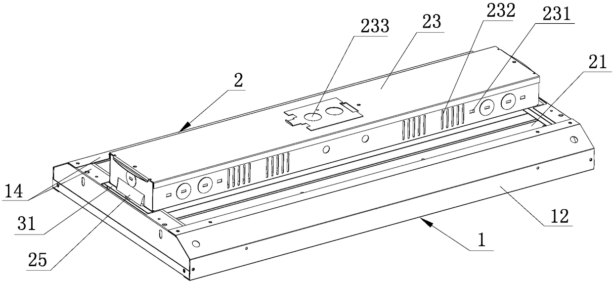
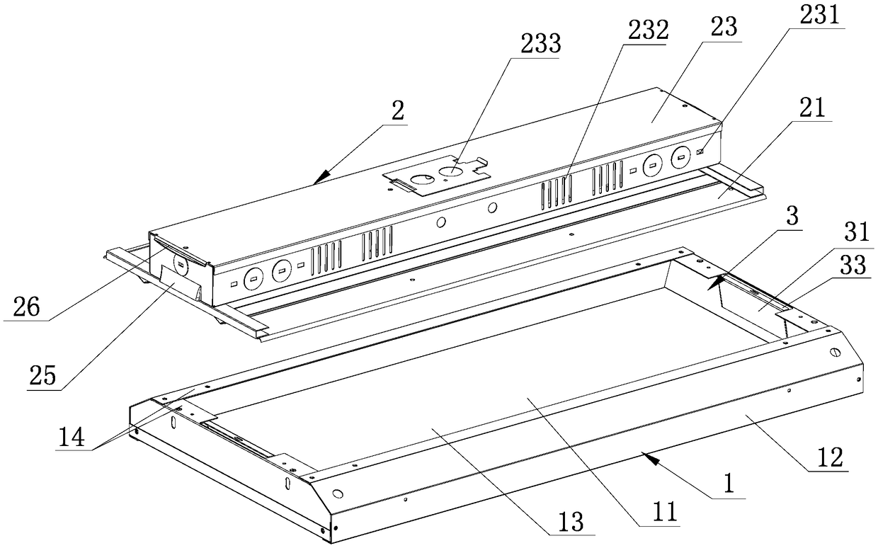
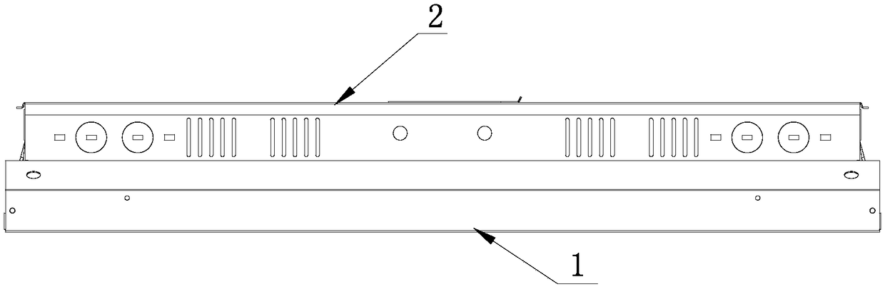
[0027] A retractable LED bracket lamp proposed by the present invention, as shown in the figure, includes a light-transmitting cover 1 and a photoelectric module 2, and the light-transmitting cover 1 has a square concave cavity that can be used as a cooling cavity and a storage cavity 11. The light-transmitting cover 1 is composed of a frame-shaped support 12 and a light-transmitting plate 13. The light-transmitting plate 13 is arranged on the bottom of the frame-shaped support 12, so that the incident surface of the light-transmitting plate 13 is surrounded by the inner side of the frame-shaped support 12. Form a square concave cavity 11. The light-transmitting cover 1 of this structure is not only simple in structure, but also easy to form a square concave cavity 11. The two ends of the inner side of the square concave cavity 11 are symmetric...


PUM


Abstract

The invention discloses a telescopic LED bracket lamp. The telescopic LED bracket lamp comprises a light pervious cover and a photoelectric module, wherein the light pervious cover is provided with asquare concave cavity which can be used as a heat dissipation cavity, and also can be used as a storage cavity; and the photoelectric module is movably connected with the square concave cavity. When the LED bracket lamp is used, the square concave cavity is used as the heat dissipation cavity; and the photoelectric module is upwards pulled, so that the photoelectric module is fixedly arranged above a cavity mouth of the square concave cavity. When the LED bracket lamp is not used, the square concave cavity is used as the storage cavity, and the photoelectric module is downwards pushed, so thatthe photoelectric module is embedded into the square concave cavity, and the photoelectric module is not in contact with the cavity bottom of the square concave cavity. The telescopic LED bracket lamp has the advantages of being small in integral thickness and small in size when the lamp is packaged, transported and not used, and good in heat dissipation effect when not used.

Description

technical field [0001] The invention relates to an LED lamp, in particular to a retractable LED bracket lamp. Background technique [0002] LED bracket light is a direct-down lighting fixture installed on the ceiling, which is usually used in shopping malls, classrooms, warehouses and other places. [0003] Existing LED bracket lights usually include a bracket base, an LED light source, a driving power supply and a light-transmitting cover. In order to make the structure more compact, the LED light source and driving power are generally installed on the inner bottom surface of the bracket base, and the light-transmitting cover is arranged on the bracket base. Above the inner bottom surface of the LED light source and the driving power are sealed in the airtight space formed by the support base and the transparent cover. When the LED bracket light with this structure is working, the LED light source and the driving power supply will generate heat at the same time, and the tw...

Claims


Application Information

Patent Timeline
IPC IPC(8): F21S8/04F21V21/22F21V29/50F21V29/83F21V17/10F21V23/00F21Y115/10
CPCF21S8/04F21V17/10F21V21/22F21V23/00F21V29/50F21V29/83
Inventor 陈静安胡君乐陈天荣李阳
Owner ZHEJIANG SUNSHINE MEIJIA LIGHTING CO LTD
Why Eureka
Try Eureka