
Water inflow insulating pipe and electric water heater

An insulating pipe and water inlet technology, which is applied in the direction of fluid heaters, lighting and heating equipment, etc., can solve problems such as failure to meet the normal bathing requirements of users, generation of scale, and turbulent water flow in the inner tank.

Pending Publication Date: 2019-02-05
QINGDAO ECONOMIC & TECHN DEV ZONE HAIER WATER HEATER
View PDF0 Cites 0 Cited by
  • Summary
  • Abstract
  • Description
  • Claims
  • Application Information

AI Technical Summary

Problems solved by technology

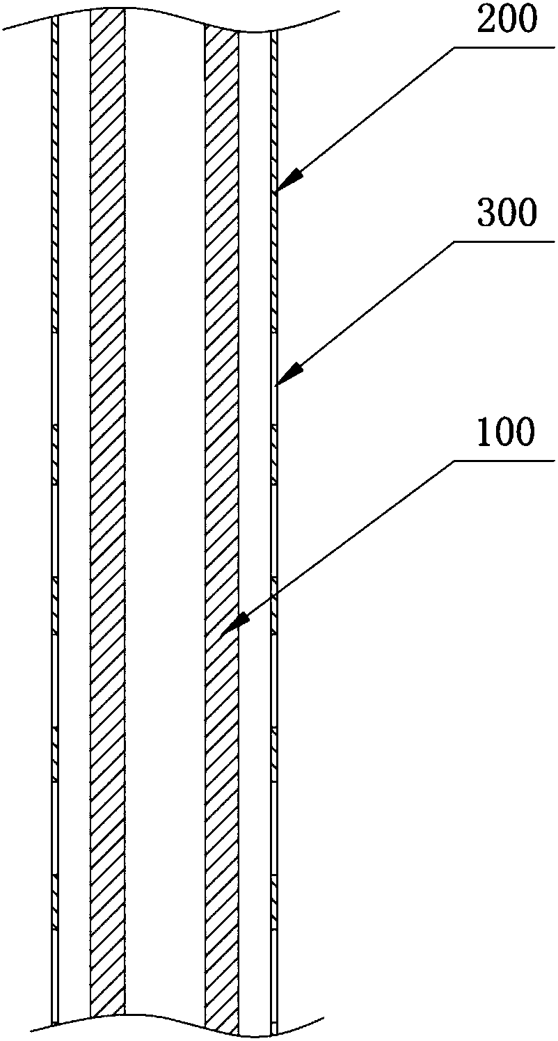
[0002] The water inlet insulating pipe is an important part of the cold water inlet of the electric water heater. At present, the water inlet insulating pipe in the industry is as follows: figure 1 As shown, it includes an insulating pipe 100 and a water inlet liner 200. Several water outlets 300 are opened on the water inlet liner 200, and the direction of the water outlets is mostly set in a horizontal direction, that is, tap water will pass through the water inlet after entering the insulating pipe 100. The water outlet 300 reserved on the liner 200 (usually a square hole, a round hole or an oval hole) flows into the inner tank. Since the outlet direction of the water outlet 300 on the water inlet liner 200 is horizontal, the The water flowing out of the 300 will flow in the horizontal direction, causing the water flow in the inner tank to be turbulent, which will cause a large amount of cold water to mix with the heated hot water at the bottom of the inner tank, so that the temperature of the hot water at the bottom of the inner tank will drop rapidly, and the output of hot water will be reduced. Less, unable to meet the normal bathing requirements of users
[0003] Moreover, since the water outlet 300 of the above-mentioned water inlet insulation pipe is set in the horizontal direction, there will be no water flow at the bottom of the inner tank, resulting in the deposition of impurities in the water and the generation of scale

Method used


Image

  • Water inflow insulating pipe and electric water heater
  • Water inflow insulating pipe and electric water heater
  • Water inflow insulating pipe and electric water heater

Examples


Embodiment Construction

[0023] The technical solutions of the present invention will be further described below in conjunction with the accompanying drawings and through specific implementation methods.

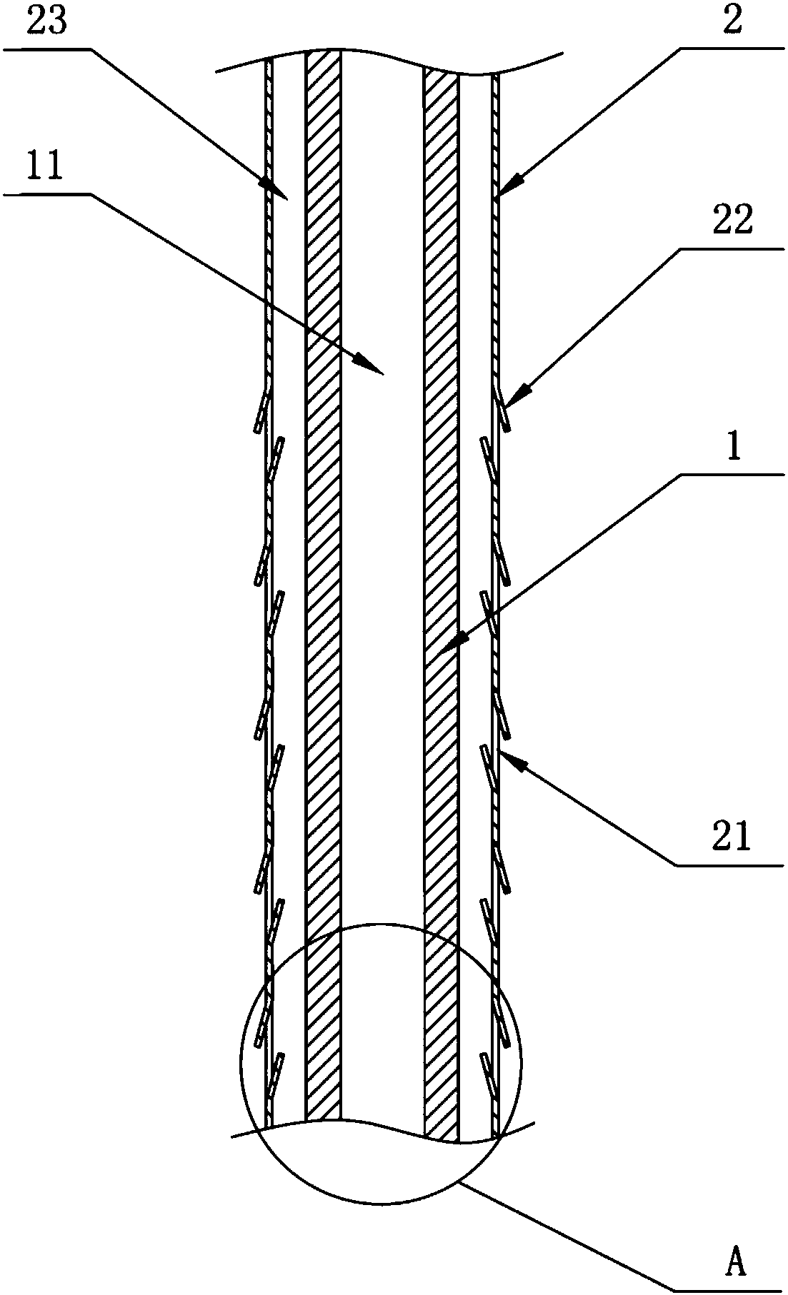
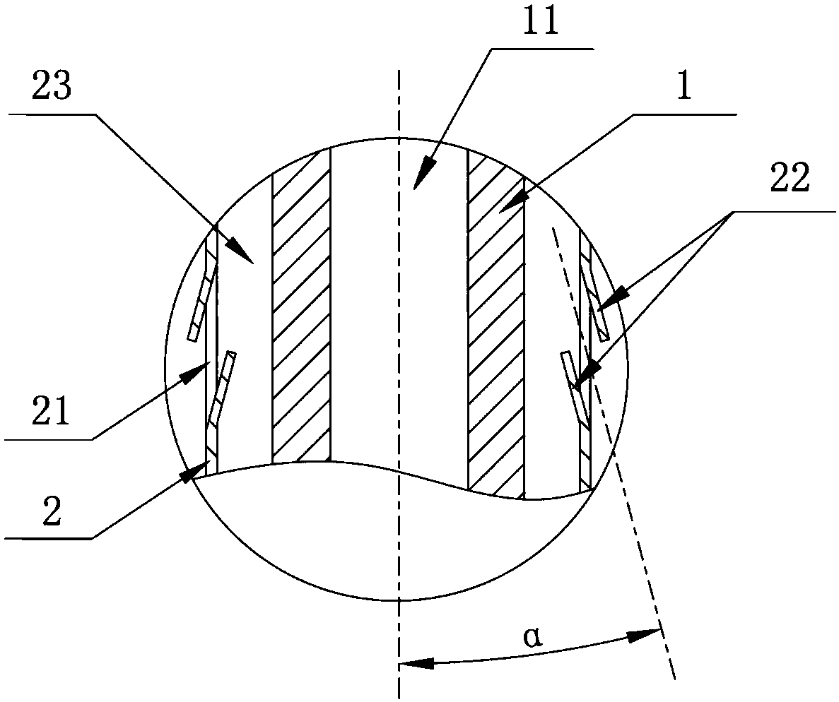
[0024] The present invention provides a water inlet insulating pipe 10, which can be used in conjunction with an inner tank 20 of an electric water heater, such as figure 2 and image 3 As shown, the water inlet insulating pipe 10 includes an insulating pipe 1 and a water inlet liner 2. On the wall of the lower end of the water inlet liner 2, there are several water outlets 21 arranged obliquely downward. Specifically, the water inlet liner 2 It is sleeved outside the insulating tube 1 and forms a water flow channel 23 between the insulating tube 1. There is a channel 11 inside the insulating tube 1. The tap water flows into the water flow channel 23 through the channel 11 of the insulating tube 1, and finally passes through the water outlet 21. Flow to the lower end of the inlet liner 2.

[0025...


PUM


Abstract

The invention belongs to the technical field of electric water heaters, and discloses a water inflow insulating pipe and an electric water heater. The water inflow insulating pipe comprises an insulating pipe body and a water inflow liner pipe; the pipe wall of the lower end of the water inflow liner pipe is provided with a plurality of obliquely and downwardly arranged water outlets; and water flows out of the water outlets and obliquely flows to the lower end position of the water inflow liner pipe. According to the water inflow insulating pipe, due to the obliquely and downwardly arranged water outlets, cold water obliquely flows to the lower end position of the water inflow liner pipe through the water outlets, that is, the cold water flows to the bottom of an inner container, so thatthe cold water only makes contact with hot water at the bottom position of the inner container, mixing with the hot water is reduced, lowering of the temperature of the hot water is reduced to a verylarge extent, and it is avoided that hot water outlet becomes little; and meanwhile, the cold water flowing to the bottom of the inner container can scour the bottom of the inner container and reducedeposition of impurities in water; and water originally staying at the bottom of the inner container is washed up and floats up, and the possibility of scaling at the bottom of the inner container isfurther lowered.

Description

technical field [0001] The invention relates to the technical field of electric water heaters, in particular to a water inlet insulating pipe and an electric water heater. Background technique [0002] The water inlet insulating pipe is an important part of the cold water inlet of the electric water heater. At present, the water inlet insulating pipe in the industry is as follows: figure 1 As shown, it includes an insulating pipe 100 and a water inlet liner 200. Several water outlets 300 are opened on the water inlet liner 200, and the direction of the water outlets is mostly set in a horizontal direction, that is, tap water will pass through the water inlet after entering the insulating pipe 100. The water outlet 300 reserved on the liner 200 (usually a square hole, a round hole or an oval hole) flows into the inner tank. Since the outlet direction of the water outlet 300 on the water inlet liner 200 is horizontal, the The water flowing out of the 300 will flow in the hori...

Claims


Application Information

Patent Timeline
Patent Type & Authority Applications(China)
IPC IPC(8): F24H9/00
CPCF24H9/0005
Inventor 丁建鹏孙强蔡想周赵雪森赵小勇王军
Owner QINGDAO ECONOMIC & TECHN DEV ZONE HAIER WATER HEATER
Learn More