Drop-off connector and drop-off connector assembly

A connector assembly and connector technology, which is applied to the parts, connections, electrical components, etc. of the connection device, and can solve problems such as inability to separate normally, easy self-locking, etc.

Active Publication Date: 2019-02-05
CHINA AVIATION OPTICAL-ELECTRICAL TECH CO LTD
View PDF6 Cites 2 Cited by
  • Summary
  • Abstract
  • Description
  • Claims
  • Application Information

AI Technical Summary

Problems solved by technology

[0004] The purpose of the present invention is to provide a detachable connector that can realize separation at a large inclination angle, so as to solve the technical problem that the detachment connector in the prior art is easy to self-lock and cannot be separated normally when it is pulled off by a pull cord at a large inclination angle; at the same time, the present invention The invention also provides a drop-off connector assembly using the above-mentioned drop-off connector

Method used


Image

  • Drop-off connector and drop-off connector assembly
  • Drop-off connector and drop-off connector assembly
  • Drop-off connector and drop-off connector assembly

Examples


Embodiment Construction

[0027] The specific embodiments of the present invention will be further described below in conjunction with the accompanying drawings, but not limited thereto.

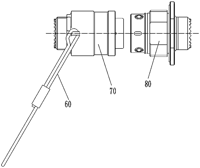
[0028] The specific embodiment of the shedding connector assembly provided by the present invention, such as Figure 4 to Figure 10 As shown, the dropout connector assembly in this embodiment includes a plug 1 and a socket 2 for corresponding mating use, and a pull cord 3 is connected to the plug 1 . It will be described below that the plug and the socket respectively use their front ends as the insertion ends.

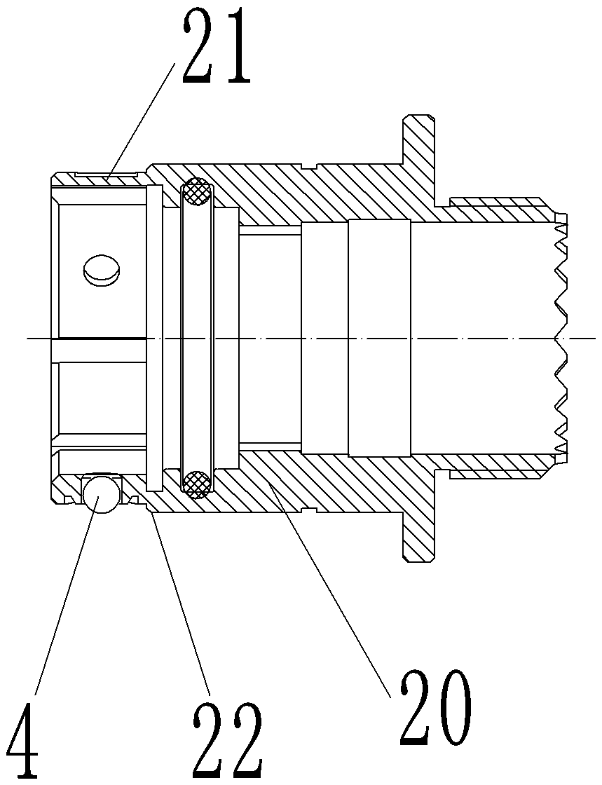
[0029] such as 7 and Figure 8 As shown, the plug 1 includes a plug housing 11, and corresponding signal contacts (not shown in the figure) are fixedly installed in the plug housing 11. The plug housing 11 is covered with a locking cap 10, and the locking cap Specifically, it is a sleeve structure, and the locking cap 10 is provided with a pushing structure for pushing the plug housing to move backward whe...


PUM


Abstract

The invention relates to a drop-off connector and a drop-off connector assembly. The drop-off connector assembly comprises a plug having a front end as a plug end and a socket. The plug comprises a plug housing, a locking connection cap sleeves a plug housing. The locking connection cap is provided with a pushing structure for pushing the plug housing backwards when the locking connection cap moves backward to realize separation of the plug and the socket, and the front end of the locking connection cap is provided, the front end of the locking connection cap is provided with a pull cord connecting lug for connecting a pull cord so that the pull cord can pull the locking connection cap back. A pull cord connecting lug is arranged at the front end of the locking connection cap to facilitatethe connection of the pull cord. The application point of the pulling force applied by the pull cord to the locking connection cap is also located at the front end of the locking hood, so that the bending moment caused by the pulling force of the pull cord on the plug is always zero. The problem that the locking hood and the socket are self-locking and cannot be separated under the large tiltingpulling force is solved.

Description

technical field [0001] The invention relates to a drop connector and a drop connector assembly. Background technique [0002] Existing shedding connectors such as outer steel ball locking push-pull shedding connectors and pull match shedding connectors, as well as other forms of locks between the connector and the mating connector are achieved by pulling the connector jacket through the pull cord to To realize the unlocking structure, the structure of the outer steel ball locking push-pull type fall-off connector is as follows: figure 2 and image 3 As shown, here is mainly to illustrate the principle of mating locking and separation unlocking, and the relevant signal transmission components inside the connector are not shown in the drawings. The plug 70 includes a plug inner shell 71 and a locking cap 72 set outside the plug inner shell. The locking cap 72 is in the shape of a sleeve. The locking cap 72 and the plug inner shell 71 are formed at the front end The insertio...

Claims


Application Information

Patent Timeline
Patent Type & Authority Applications(China)
IPC IPC(8): H01R13/627H01R13/633
CPCH01R13/6276H01R13/633
Inventor 庞卓王鹏赵聪
Owner CHINA AVIATION OPTICAL-ELECTRICAL TECH CO LTD
Why Eureka
Try Eureka