Air pressure massager

A technology of air pressure and massager, which is applied in the direction of pneumatic massage, auxiliary products for massage, instruments for compressing reflex points, etc., and can solve problems such as unusable, piston noise, and rising pistons

Inactive Publication Date: 2019-02-05
李昌宰
View PDF10 Cites 6 Cited by
  • Summary
  • Abstract
  • Description
  • Claims
  • Application Information

AI Technical Summary

Problems solved by technology

[0005] So the technique of raising the piston via the return spring does not utilize 100% of the limited amount of air and has the problem of making noise when the piston starts to rise

Method used


Image

  • Air pressure massager
  • Air pressure massager
  • Air pressure massager

Examples


Embodiment Construction

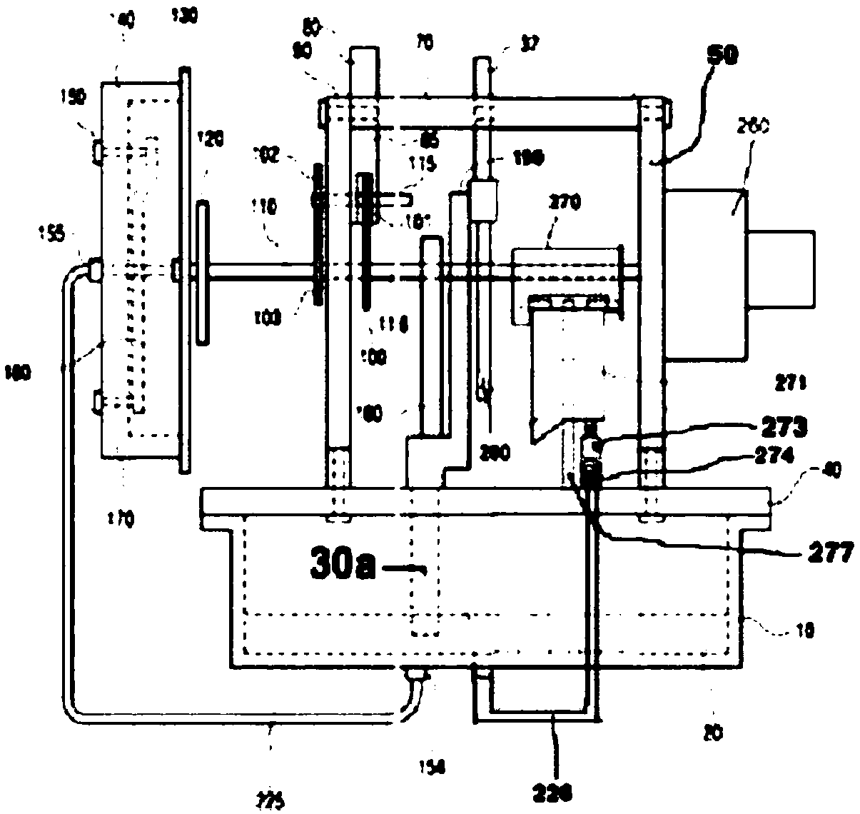
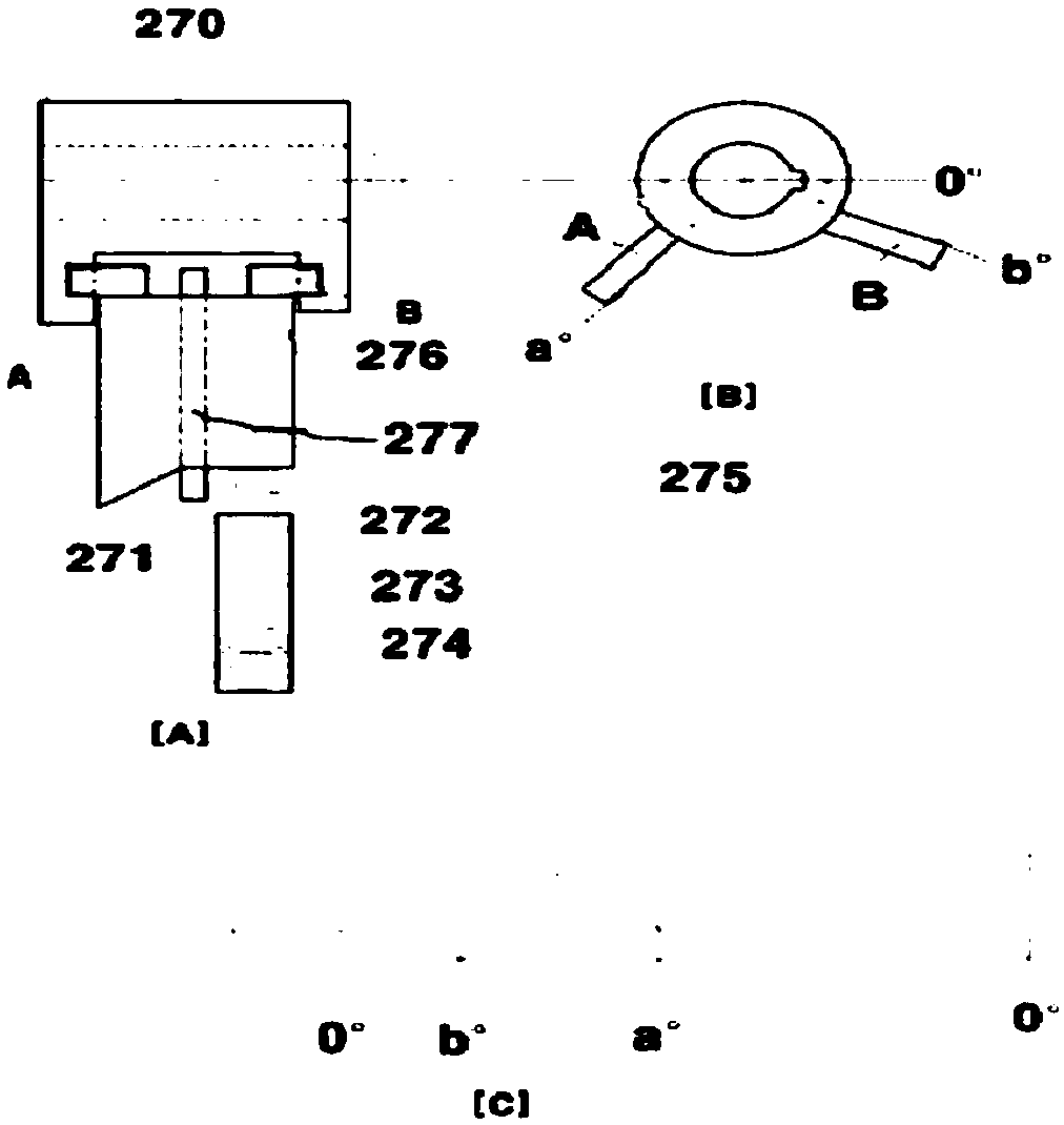
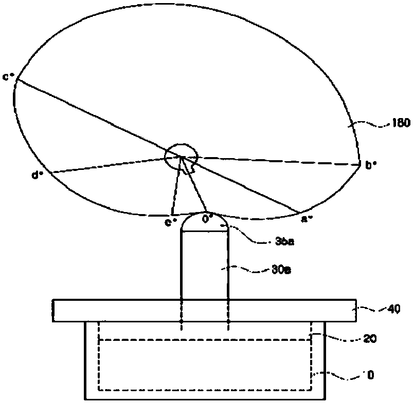
[0029] The air pressure massager of the present invention includes a cylinder, a reciprocating piston in the cylinder, a main hose connected to the cylinder as a supply and recovery passage of air through the reciprocating movement of the piston, a main hose connected to the main hose A valve to open and close the supply of air pressure, an air bag using the air pressure connected to the valve as an acupressure action, and a drive unit for providing rotational power, as the air pressure massager includes a rotary shaft connected to the drive unit, The first eccentric cam connected to the rotating shaft, the upper end against the lower end of the first eccentric cam, the lower end combined with the upper end of the piston, the second eccentric cam connected to the rotating shaft, the lower end A second pressing rod abutted against the upper end of the second eccentric cam and a connecting rod for connecting the first pressing rod and the second pressing rod, the rods on both sid...


PUM


Abstract

The invention relates to an air pressure massager. The air pressure massager according to the invention comprises: a cylinder; a piston vertically reciprocating inside the cylinder; a main hose connected to the cylinder so as to be a passage for supplying and recovering air by the vertical reciprocation of the piston; a valve connected to the main hose so as to open and close the supply of air pressure; an air bag connected to the valve so as to perform an acupressure function by using the transferred air pressure; and a driving part for providing rotational power, and further includes: a rotary shaft coupled to the driving part; a first eccentric cam coupled to the rotary shaft; a first press bar of which the upper end portion comes into contact with the lower end portion of the first eccentric cam and of which the lower end portion is coupled to the upper end portion of the piston; a second eccentric cam coupled to the rotary shaft; a second press bar of which the lower end portion comes into contact with the upper end portion of the second eccentric cam; and a link for connecting the first press bar and the second press bar. The air pressure massager is configured such that whenthe first press bar moves downward by the eccentric rotation of the first eccentric cam, the second press bar connected to the first press bar by the link also moves downward, and when the second press bar moves upward by the eccentric rotation of the second eccentric cam, the first press bar connected to the second press bar by the link also moves upward.

Description

technical field [0001] The present invention relates to a device for continuously massaging a body part by intermittently pressing a body part to be massaged by using expansion force and contraction force of an air bag generated when a piston is moved up and down while air in the air bag is supplied and recovered in the air bag. Background technique [0002] In the patent No. 10-0835755 authorized by the present inventor, a high-performance meridian massage machine is disclosed. When the piston is lowered by rotating the eccentric cam, the air in the cylinder enters the air bag through the hose, and an expansion force is generated in the air bag. [0003] After pressing the body part with the expansion force, the piston rises by the elasticity of the return spring, when the air supplied to the airbag is almost recovered into the cylinder and the air volume in the airbag becomes thinner, the piston rises, at this time, when the air that is sucked into the cylinder When the ai...

Claims


Application Information

Patent Timeline
Patent Type & Authority Applications(China)
IPC IPC(8): A61H9/00A61H39/04
CPCA61H9/0078A61H2201/0169A61H2201/1246A61H2201/1418A61H2201/5002A61H2201/5053A61H2201/1409A61H2201/149A61H39/04A61H9/005A61H9/00A61H2205/06A61H2205/081A61H2205/10
Inventor 李昌宰
Owner 李昌宰
Why Eureka
Try Eureka