Three-axis control stick

A technology for controlling parameters and control systems, which is applied in the directions of aircraft control, control start-up methods, human manipulation, etc.

Active Publication Date: 2019-02-05
拉蒂尔菲雅克股份有限公司
View PDF6 Cites 0 Cited by
  • Summary
  • Abstract
  • Description
  • Claims
  • Application Information

AI Technical Summary

Problems solved by technology

However, there is still a need for improved components for control systems in the prior art

Method used


Image

  • Three-axis control stick
  • Three-axis control stick
  • Three-axis control stick

Examples


Embodiment Construction

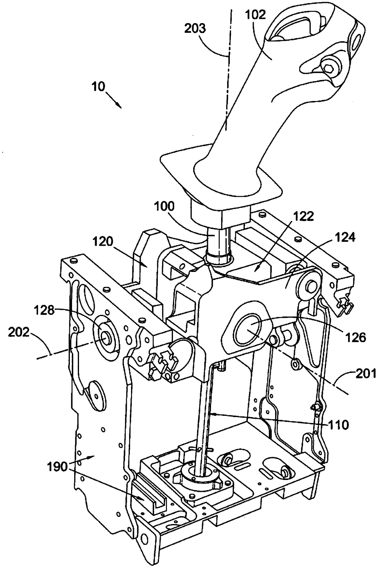
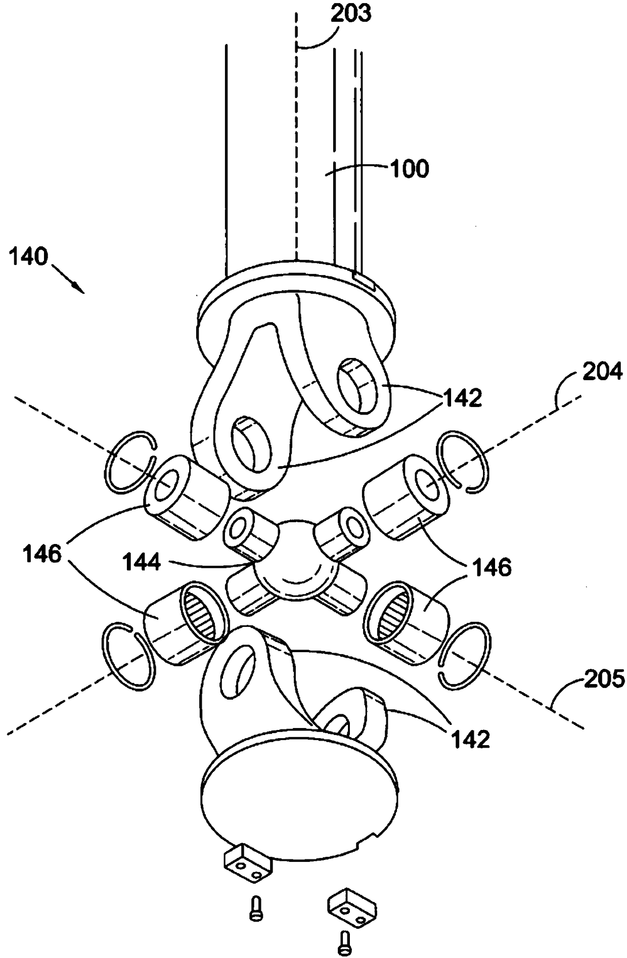
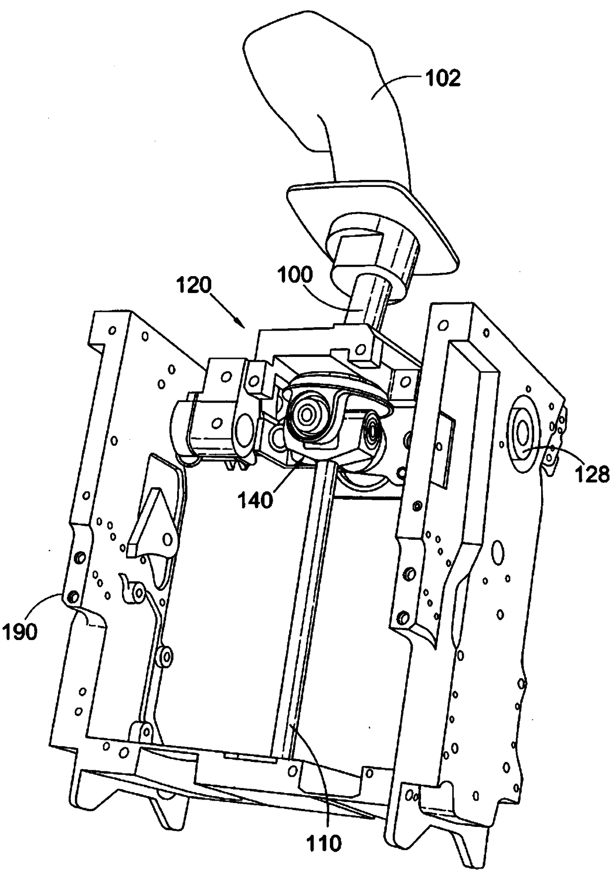
[0039] Reference will now be made to the drawings, wherein like reference numerals represent like structural features or aspects of the present disclosure. For purposes of illustration and description, but not limitation, figure 1 An illustrative view of an embodiment of a joystick module according to the present disclosure is shown in and generally designated by the reference numeral 10 . Figure 2 to Figure 4 Other aspects of the disclosure are shown in . The components described herein can be used to control the dynamics and / or movements of the system. For example, the components may control flight control parameters of aircraft, movement parameters of watercraft such as submarines, hydrofoils, hovercraft, etc., control parameters of all-terrain vehicles, tanks, drones, jetpacks, wheelchairs, remote control systems and / or simulators.

[0040] figure 1 A joystick module 10 is shown comprising a first shaft 100 , a second shaft 110 and a gimbal mechanism 120 supported wit...


PUM


Abstract

There is provided a control stick module (10) comprising: a first shaft (100); a second shaft (110); a joint (140) connecting the first and second shafts; and a gimbal mechanism (120); wherein the joint is nested within the gimbal mechanism. The gimbal mechanism provides axes of rotation (201, 202) for the first shaft (100) and the joint provides axes of rotation (203, 204, 205) for the first shaft (100); and the axes of rotation (201, 202) provided by the gimbal mechanism intersect at a point corresponding to a point of intersection of the axes (203, 204, 205) provided by the joint.

Description

technical field [0001] The present disclosure relates to an assembly for a control system, such as an assembly for a control system including a three-axis joystick. Background technique [0002] In a vehicle, components for a control system are provided to control at least some of the movement or dynamics of the vehicle. For example, in vehicles such as airplanes, helicopters or ships, joysticks may be provided to control dynamics such as pitch and roll. In general, other control features may also be provided to control other dynamics. For example, pedals and / or sticks may control rudder and / or yaw of the vehicle. [0003] Some systems combine the control of multiple dynamics into a single system. A three-axis joystick may, for example, be arranged to control pitch, roll and yaw of the vehicle by allowing rotation of the joystick about three axes. However, combining more and more control capabilities into a single system requires increasing the complexity of the system n...

Claims


Application Information

Patent Timeline
IPC IPC(8): B64C13/04
CPCB64C13/0421Y02T50/40B64C13/04
Inventor J-P.卡里
Owner 拉蒂尔菲雅克股份有限公司
Why Eureka
Try Eureka