Supercharge Your Innovation With Domain-Expert AI Agents!

Embroidery machine, in particular shuttle embroidery machine

An embroidery machine and embroidery technology, which are applied to the mechanism of the embroidery machine, the mechanism that cuts off the thread in the embroidery machine, and the sewing machine, etc., can solve the problems of large thread consumption, increased wear and vibration of the embroidery machine, etc., so as to simplify the modification work and shorten the downtime. Time and spare parts replacement cost reduction effect

Inactive Publication Date: 2019-02-05
LAESSER AG
View PDF1 Cites 0 Cited by
  • Summary
  • Abstract
  • Description
  • Claims
  • Application Information

AI Technical Summary

Problems solved by technology

This may cause vibration and noise, and increase wear and tear on the embroidery machine
Furthermore, the disadvantage of this device is that the upper thread is cut relatively far away from the embroidery hole plate and the embroidery material on it, which leads to a high consumption of thread, and moreover, the thread ends on the embroidery cloth must be removed later
In addition, the proven disadvantage is that, if not necessary, the already clamped thread can be released again by the joint action of the cutter or the jaws

Method used


Image

  • Embroidery machine, in particular shuttle embroidery machine
  • Embroidery machine, in particular shuttle embroidery machine
  • Embroidery machine, in particular shuttle embroidery machine

Examples


Embodiment Construction

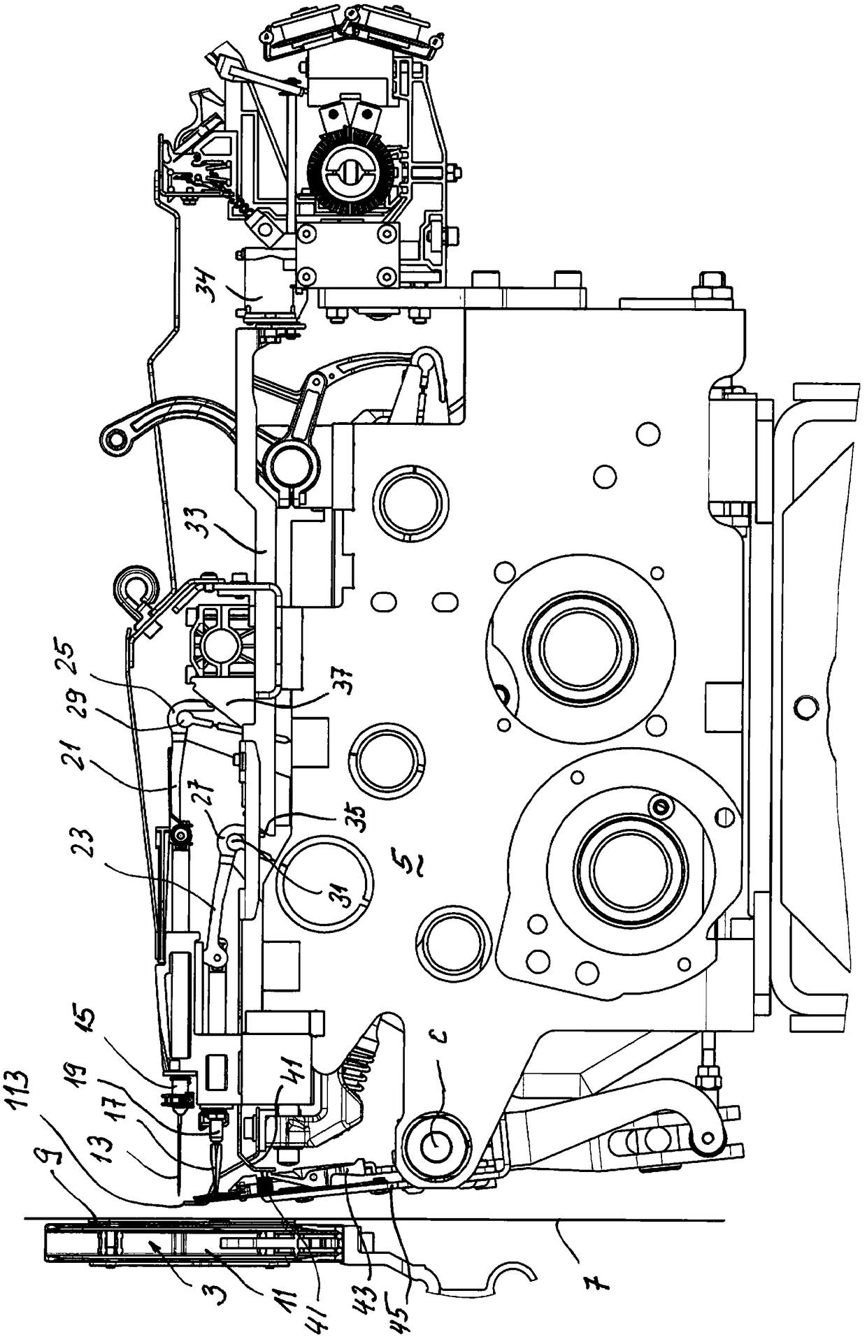
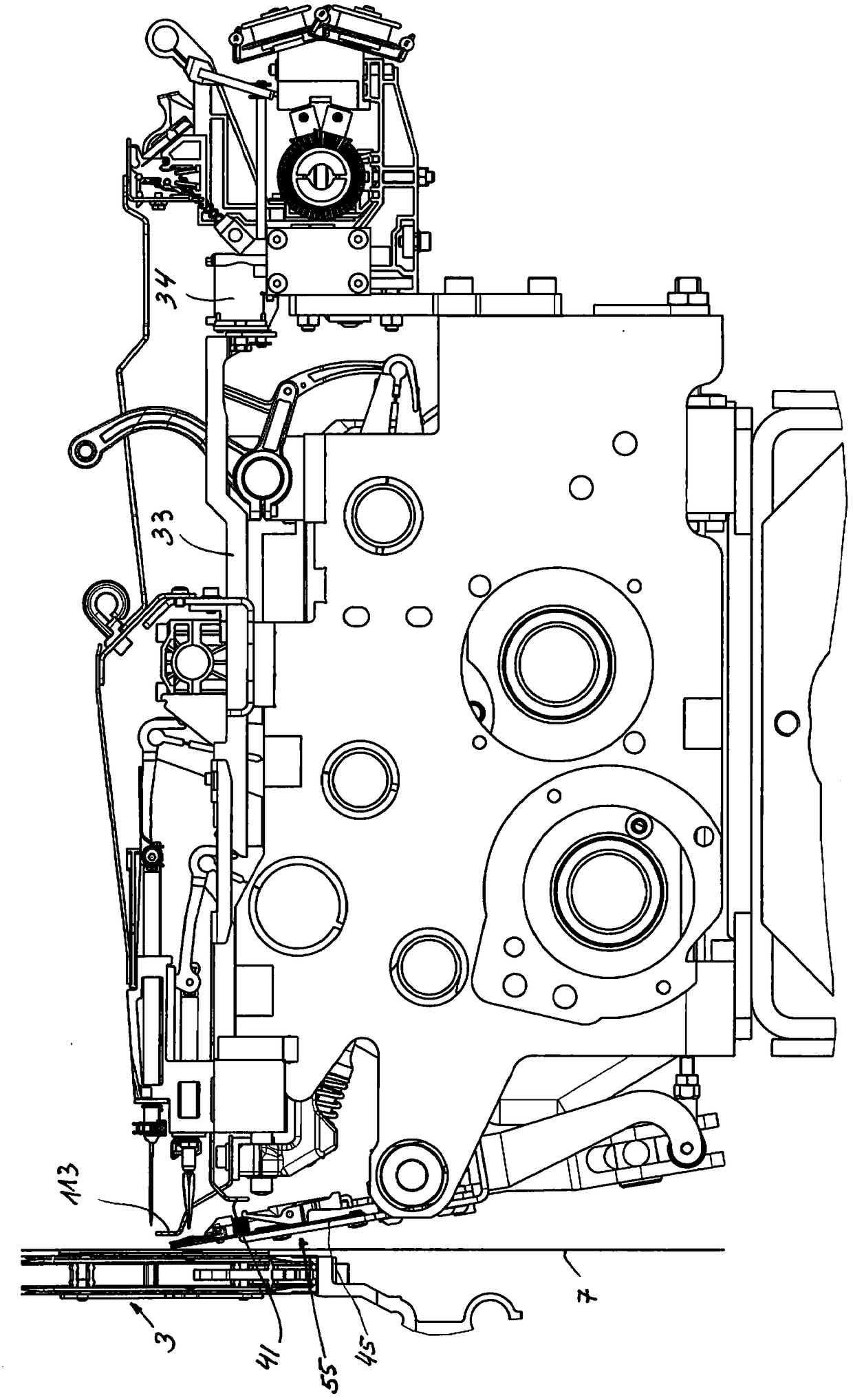
[0029] exist figure 1 and figure 2 In, in order to understand the present invention, the necessary components in a large shuttle car embroidery machine are described. In these figures, it is especially clear to see the Between 3 and the needle car 5 is an embroidery thread cutting and clamping device for cutting and clamping needle thread or upper thread—hereinafter referred to as embroidery thread cutting and clamping device 1 . shuttle track 3 is movable around an axis not shown here to facilitate access to the embroidery base 7 between the embroidery hole plate 9 and the needle 15. On the embroidery base plate 7 and the shuttle rail An embroidery orifice 9 is arranged between the 3. For better visibility, the shuttle track 3. The shuttle car in the shuttle car track 11 is omitted.

[0030] On the right side of the embroidery base plate 7, above the needle 13, it can be seen that it is clamped by the needle holder 15. Below the needle 13 is a drill 17 which is h...


PUM


Abstract

The invention relates to an embroidery machine, comprising a thread cutting and thread clamping device (1) for cutting and clamping the needle threads. An autonomous thread cutting and thread clampingelement (55) is arranged on a carrier plate (45) for each embroidery position and can be driven. Each individual thread cutting and thread clamping element (55) can individually be switched on or offby means of a drive.

Description

technical field [0001] The object of the invention is an embroidery machine, in particular a shuttle car embroidery machine, according to the general concept of claim 1 . Background technique [0002] In EP 0 768 418, an upper thread cutting and clamping device for cutting upper thread, also known as needle thread, is described, wherein a cloth pressing finger or claw has been designed on the cloth pressing plate, and a Cutter ruler that moves vertically. On this cutter ruler, the thread catcher is provided with an angled end for catching the upper thread leading from the needle to the fabric. In addition, a hooked knife is designed on the cutter ruler, a blade or cutter formed on the cloth press plate, which cuts the thread caught by the grapple if the cutter is guided downwards relative to the cloth press plate. Using this known device, all the threads extending between the cloth and the embroidery needle can be cut simultaneously, in addition, the thread end drawn by th...

Claims


Application Information

Patent Timeline
Patent Type & Authority Applications(China)
IPC IPC(8): D05C11/20D05B65/00
CPCD05C11/20D05B65/00
Inventor 法兰兹·拉瑟
Owner LAESSER AG
Features
  • R&D
  • Intellectual Property
  • Life Sciences
  • Materials
  • Tech Scout
  • Unparalleled Data Quality
  • Higher Quality Content
  • 60% Fewer Hallucinations
Learn More