Supercharge Your Innovation With Domain-Expert AI Agents!

Compressor with variable compressor inlet

A technology for compressors and compressor casings, which is applied in machine/engine, mechanical equipment, engine manufacturing, etc., can solve problems such as no longer, low efficiency, etc., and achieve the effect of reducing the impact

Inactive Publication Date: 2019-02-05
BORGWARNER INC
View PDF0 Cites 0 Cited by
  • Summary
  • Abstract
  • Description
  • Claims
  • Application Information

AI Technical Summary

Problems solved by technology

Depending on the size and configuration of the compressor, low volume flow operation of the compressor may be inefficient or no longer possible because the surge limit is not reached

Method used


Image

  • Compressor with variable compressor inlet
  • Compressor with variable compressor inlet
  • Compressor with variable compressor inlet

Examples


Embodiment Construction

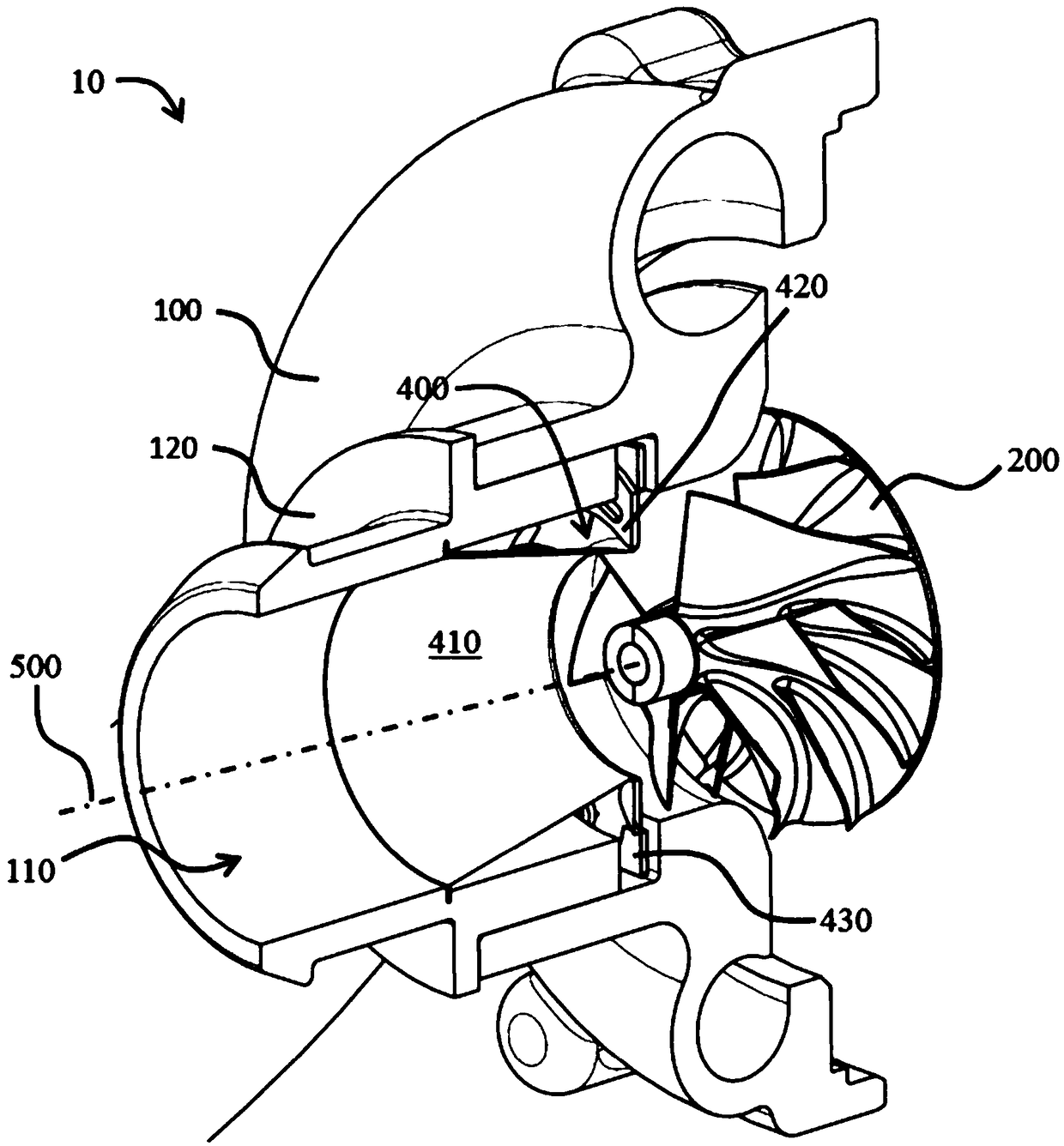
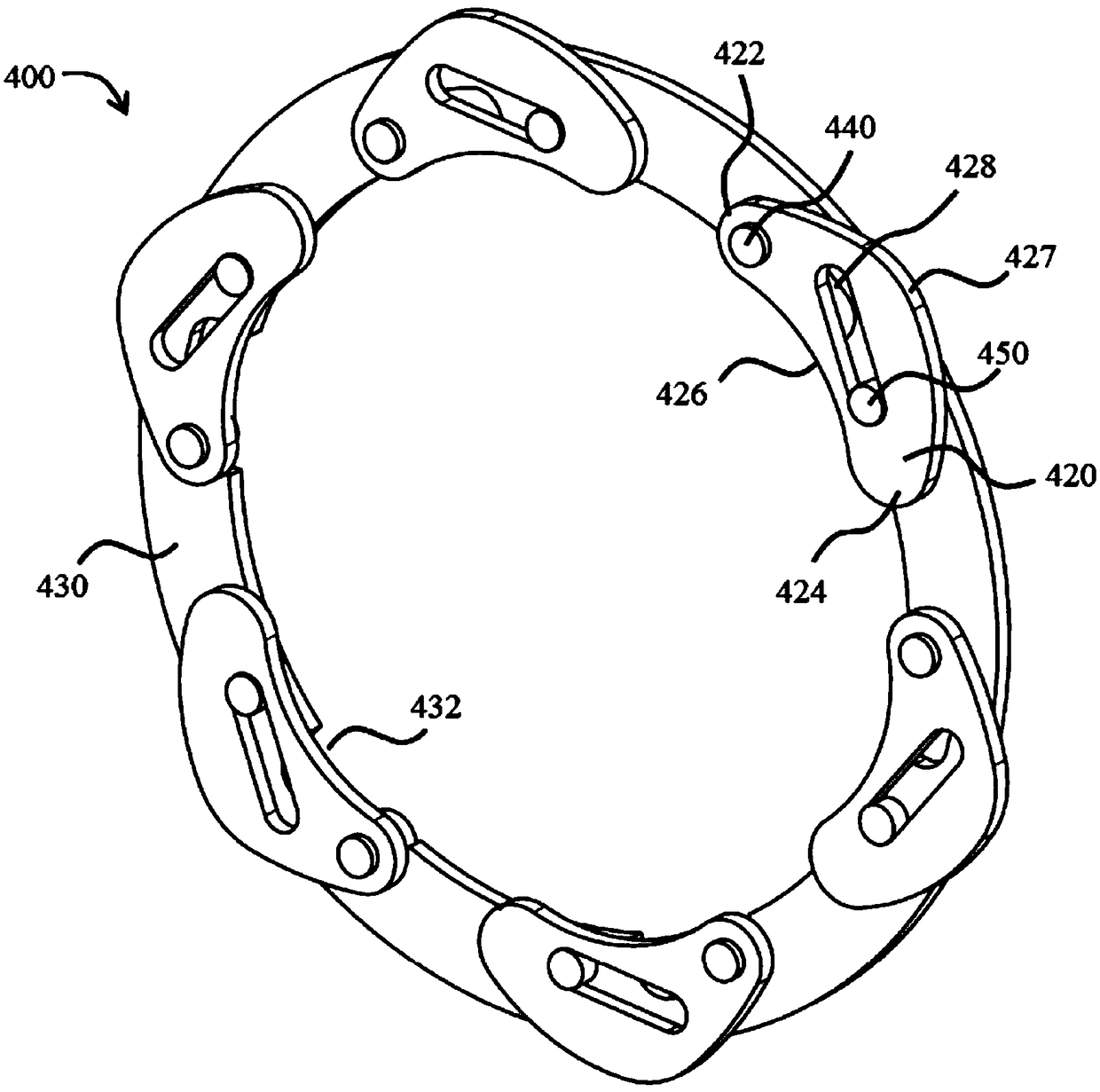
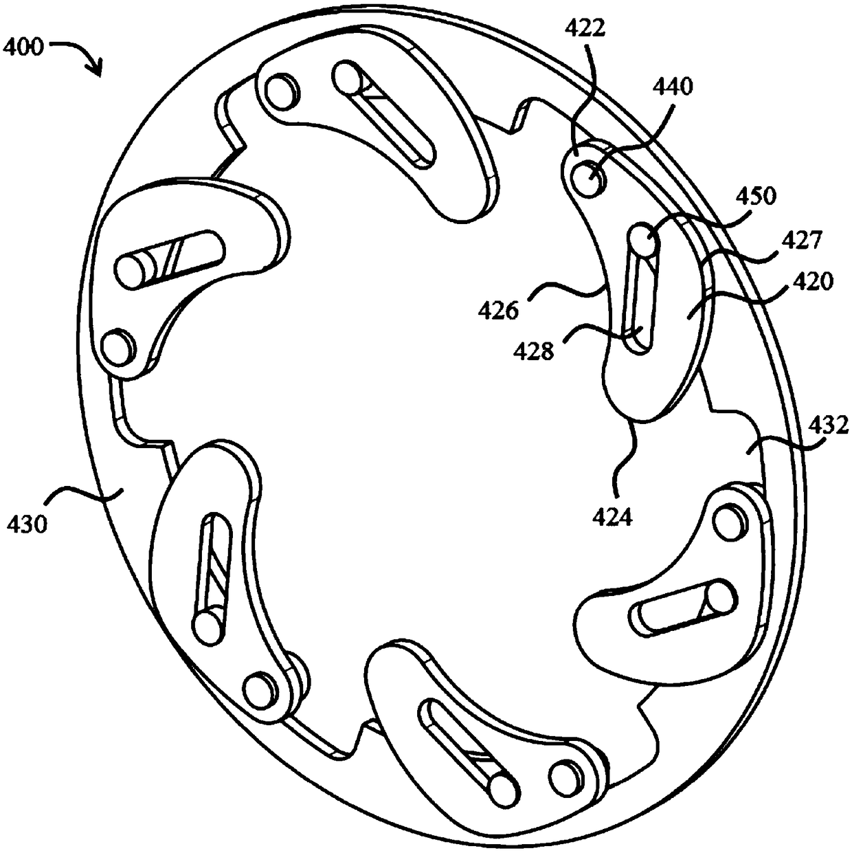
[0028] In the following, an embodiment of the compressor 10 according to the invention and also the regulating mechanism 400 according to the invention will be described by means of the drawings. All details and advantages described subsequently apply both to the adjusting mechanism 400 and to the compressor 10 comprising such an adjusting mechanism 400 and also to the charging device comprising the corresponding compressor 10 . The charging device can be, for example, an exhaust-gas turbocharger with a turbine, an electrically supported exhaust-gas turbocharger with a turbine and an electric motor, or a compressor 10 driven exclusively by an electric motor. Within the scope of the present application, a radial surface / lateral plane refers to a surface arranged substantially perpendicular to the axis of rotation 500 of the compressor 10 .

[0029]figure 1 An isometric cutaway view of one embodiment of a compressor 10 according to the present invention is shown. In the followi...


PUM


Abstract

An adjusting mechanism (400) for a compressor of a charging device for the variable changing of the cross section of a compressor inlet, comprising an adjusting ring (430), a plurality of adjusting elements (420) which are rotatably mounted and coupled to the adjusting ring, and a trimming device (410) which defines an inlet cross section. The adjusting elements are coupled to the trimming deviceso that a movement of the adjusting elements causes an adjustment of the trimming device. The adjustment of the trimming device causes a change in the inlet cross section.

Description

technical field [0001] The invention relates to an adjustment mechanism for a compressor, a compressor comprising a corresponding adjustment mechanism, and a charging device comprising a corresponding compressor. Background technique [0002] Vehicles of the latest generation are increasingly equipped with supercharging devices. In order to meet target requirements and legal requirements, it is imperative to promote the development of the entire drive train and to optimize individual components as well as the entire system in terms of reliability and efficiency. [0003] Exhaust-gas turbochargers are known, for example, in which a turbine with a turbine wheel is driven by the flow of exhaust gas from an internal combustion engine. A compressor with a compressor wheel, which is arranged on a common shaft together with the turbine wheel, compresses the fresh air taken in by the engine. In this way, the total amount of air or oxygen available to the engine for combustion is i...

Claims


Application Information

Patent Timeline
IPC IPC(8): F04D25/04F02B37/22F04D27/02F04D29/42F04D29/46
CPCF02B37/225F04D25/04F04D27/0253F04D29/4213F04D29/464F05D2220/40F05D2250/51Y02T10/12
Inventor S·卡尔施泰特W·亨克
Owner BORGWARNER INC
Features
  • R&D
  • Intellectual Property
  • Life Sciences
  • Materials
  • Tech Scout
  • Unparalleled Data Quality
  • Higher Quality Content
  • 60% Fewer Hallucinations
Learn More