
Facilitating robot positioning

A technology of robots and cameras, which is applied in the field of machines and can solve problems such as precision

Active Publication Date: 2019-02-05
ABB (SCHWEIZ) AG
View PDF16 Cites 4 Cited by
  • Summary
  • Abstract
  • Description
  • Claims
  • Application Information

AI Technical Summary

Problems solved by technology

For example, both methods require calibration of the camera-to-robot relationship and have accuracy issues due to the use of nominal robot kinematics

Method used


Image

  • Facilitating robot positioning
  • Facilitating robot positioning
  • Facilitating robot positioning

Examples


Embodiment Construction

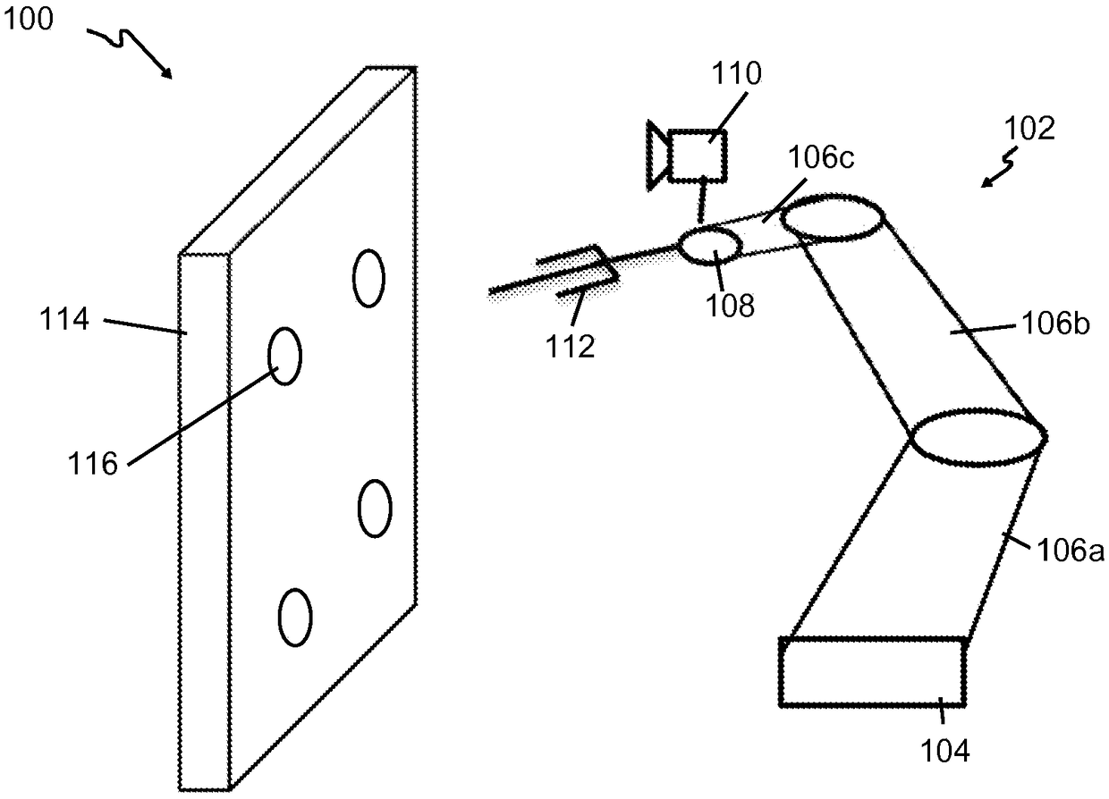
[0013] Aspects described herein relate generally to robotic 3D scanning and robotic positioning, for example, for use with an industrial robotic system that uses a robot-mounted 3D camera to scan a scene in an environment, and then positions the robot to / on the scanned features in the scene to perform the intended action. More specifically, methods for aiding in precise robot positioning are disclosed. As an example, a sensor fusion method is presented that combines robot position measurements (“robot odometry”) with an image registration method (“visual odometry”) that can be used to automatically perform camera-to-robot calibration And improve the accuracy of robot positioning. This is particularly useful for robotic applications in areas where the position or characteristic properties of objects are unknown.

[0014] One such application is by way of example and not limitation in figure 1 is depicted in , which details an example environment in which a robot works on a w...


PUM


Abstract

Robot positioning is facilitated by obtaining, for each time of a first sampling schedule, a respective indication of a pose of a camera system of a robot relative to a reference coordinate frame, therespective indication of the pose of the camera system being based on a comparison of multiple three-dimensional images of a scene of an environment, the obtaining providing a plurality of indications of poses of the camera system; obtaining, for each time of a second sampling schedule, a respective indication of a pose of the robot, the obtaining providing a plurality of indications of poses ofthe robot; and determining, using the plurality of indications of poses of the camera system and the plurality of indications of poses of the robot, an indication of the reference coordinate frame andan indication of a reference point of the camera system relative to pose of the robot.

Description

Background technique [0001] Current robot scanning and localization systems use measured robot positions or image registration methods to estimate relative camera view positions in order to register (often referred to as "stitching") the individual camera views. Each approach has advantages and disadvantages, but some issues are common to both. For example, both approaches require calibration of the camera-to-robot relationship and have accuracy issues due to the use of nominal robot kinematics. Contents of the invention [0002] The disadvantages of the prior art are overcome and additional advantages are provided by a method comprising: for each of a plurality of times of a first sampling schedule, obtaining a pose of a camera system of a robot with respect to a reference coordinate system A corresponding indication of the pose of the camera system based on a comparison of a plurality of three-dimensional images of the environmental scene, the obtained providing a plurali...

Claims


Application Information

Patent Timeline
Patent Type & Authority Applications(China)
IPC IPC(8): G05B15/00
CPCG06T2200/04G06T2207/10028G06T7/74G06T2207/30244Y10S901/09G05B2219/39057B25J9/1692B25J9/1697E21C35/08
Inventor 汪建军张飚C·马蒂内兹C·W·莫拉托R·博卡
Owner ABB (SCHWEIZ) AG
Learn More