
Garlic harvester
A harvester and garlic technology, applied to harvesters, digging harvesters, topping machines, etc., can solve the problems of inability to separate garlic heads and garlic stems, difficult labor production efficiency, time-consuming and labor-intensive, etc., and achieve simple structure and improved Labor efficiency, high efficiency effect
- Summary
- Abstract
- Description
- Claims
- Application Information
AI Technical Summary
Problems solved by technology
Method used
Image

Examples
Embodiment 1
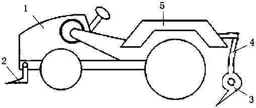
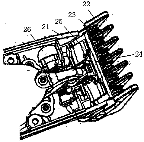
[0021] Such as figure 1 Shown, the garlic harvester of the present invention comprises vehicle body 1, harvesting head 2, coulter 3; Described body 1 is provided with diesel engine, and described harvesting head 2 is located at the below of the front end of vehicle body 1, and described Coulter 3 is located at the rear end of vehicle body 1; Described harvesting head 2 comprises knife rest 21, power sheet 22, fixed blade 23, pressure spring sheet 24 and stabilizing bolt 25, and described power sheet 22, fixed blade 23 all Set horizontally, the fixed blade 23 is fixedly mounted on the front end of the knife holder 21, the power piece 22 is arranged above the fixed blade 23, and there is a sliding seam close to the fixed blade 23; the pressure spring piece 24 is set horizontally One end of the pressure spring sheet 24 is connected with the power sheet 22, and the other end is connected with the stabilizing bolt 25, and the stabilizing bolt 25 is installed on the constant force s...
PUM
 Abstract
Description
Claims
Application Information