
Adjustable damping type Cs axis continuous machining stabilizing device

A technology of stabilizing device and adjusting damping, applied in the field of CNC lathes, can solve the problems of poor surface processing quality of workpieces, easy vibration of CNC lathes, etc., and achieves the effects of simple structure, low price, and vibration elimination.

Pending Publication Date: 2019-02-12
SHANGHAI SIGMA MACHINE TOOL
View PDF0 Cites 0 Cited by
  • Summary
  • Abstract
  • Description
  • Claims
  • Application Information

AI Technical Summary

Problems solved by technology

[0004] However, the CNC lathe is prone to vibration during milling, and the surface processing quality of the workpiece is not good.

Method used


Image

  • Adjustable damping type Cs axis continuous machining stabilizing device
  • Adjustable damping type Cs axis continuous machining stabilizing device
  • Adjustable damping type Cs axis continuous machining stabilizing device

Examples


Embodiment 1

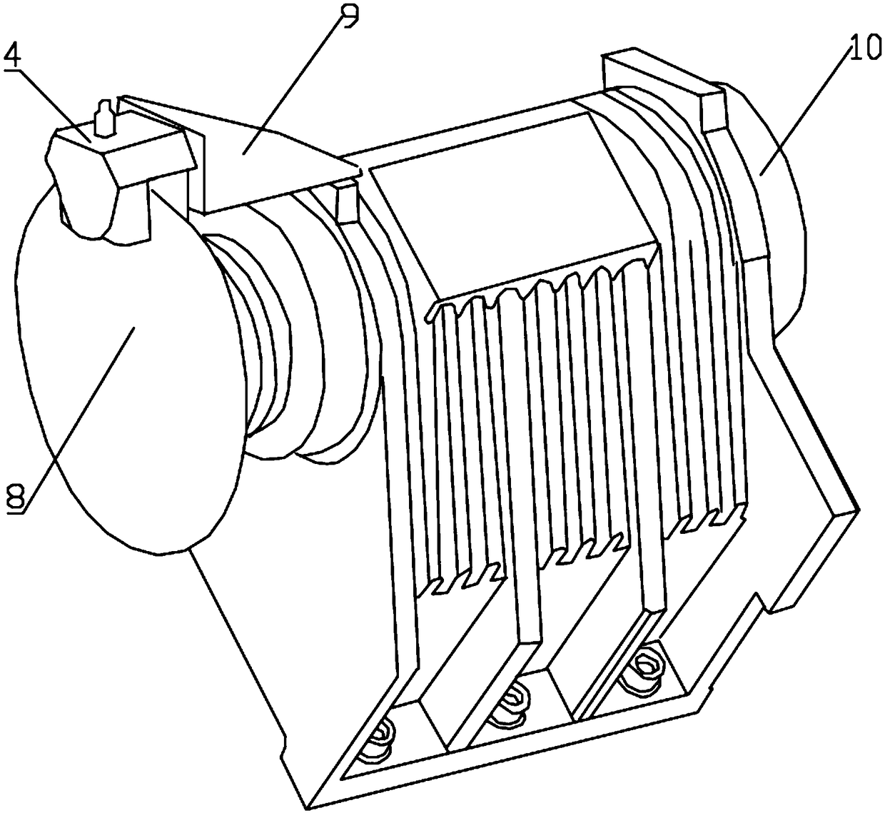
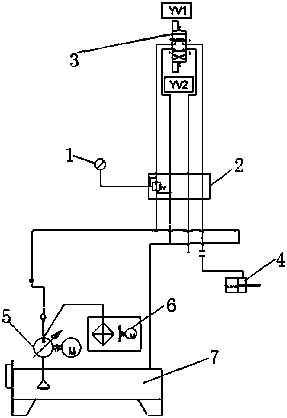
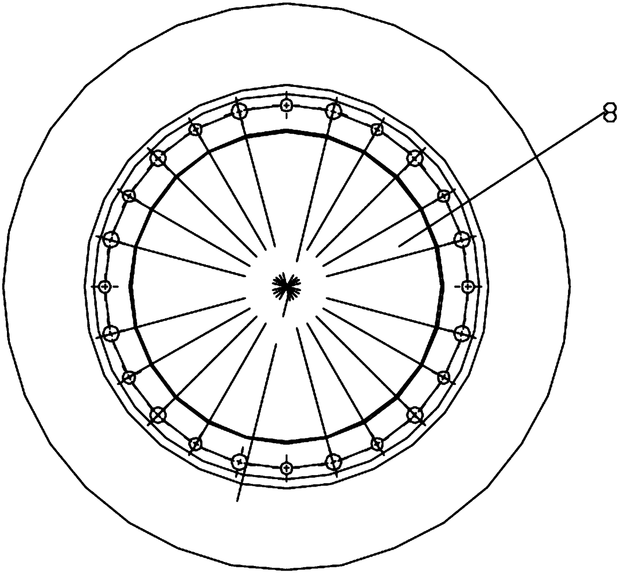
[0021] An adjustable damping type Cs-axis continuous processing stabilization device, including a mounting bracket 9, a hydraulic tank 7 and a hydraulic motor 5 are installed inside the mounting bracket 9, the hydraulic tank 7 is connected to the hydraulic motor 5, and the middle of the mounting bracket 9 A main shaft 10 is installed at the position and the main shaft 10 runs through the mounting bracket 9. A brake disc 8 is installed on the end of the main shaft 10 and a brake damping device 4 is connected to the brake disc 8. The brake damping device 4 is connected to the hydraulic tank 7, and the hydraulic motor 5 is connected to the brake disc 8. Pressure valve 2 is connected and pressure relief valve 2 is connected with reversing valve 3. The hydraulic motor 5 is connected with the cooling device 6 to facilitate the cooling of the hydraulic motor 5 and ensure the normal operation of the hydraulic motor 5 . Cooling device 6 adopts water cooling device, the technology is ma...

Embodiment 2

[0023] An adjustable damping type Cs-axis continuous processing stabilization device, including a mounting bracket 9, a hydraulic tank 7 and a hydraulic motor 5 are installed inside the mounting bracket 9, the hydraulic tank 7 is connected to the hydraulic motor 5, and the middle of the mounting bracket 9 A main shaft 10 is installed at the position and the main shaft 10 runs through the mounting bracket 9. A brake disc 8 is installed on the end of the main shaft 10 and a brake damping device 4 is connected to the brake disc 8. The brake damping device 4 is connected to the hydraulic tank 7, and the hydraulic motor 5 is connected to the brake disc 8. Pressure valve 2 is connected and pressure relief valve 2 is connected with reversing valve 3. The pressure reducing valve 2 is also connected with a pressure gauge 1, which can visually display the current pressure. The reversing valve 3 adopts a two-position four-way reversing valve, which is convenient for controlling the effec...


PUM

PropertyMeasurementUnit
Outer diameteraaaaaaaaaa
The inside diameter ofaaaaaaaaaa

Abstract

The invention discloses an adjustable damping type Cs axis continuous machining stabilizing device. The adjustable damping type Cs axis continuous machining stabilizing device comprises a mounting bracket. A hydraulic tank and a hydraulic motor are arranged in the mounting bracket. The hydraulic tank is connected with the hydraulic motor. A main shaft is arranged on the middle portion of the mounting bracket and penetrates through the mounting bracket. A brake disc is arranged on the end portion of the main shaft, and a braking damping device is connected to the brake disc and connected with the hydraulic tank. The hydraulic motor is connected with a pressure reducing valve connected with a reversing valve. The adjustable damping type Cs axis continuous machining stabilizing device is reasonable in design and simple in structure. By adjusting the pressure of a clamping device to make a mechanism generate certain damping, the vibration during Cs axis interpolation operation can be reduced or eliminated. The adjustable damping type Cs axis continuous machining stabilizing device is convenient to install and use, low in price and wide in application prospect.

Description

technical field [0001] The invention relates to the field of numerically controlled lathes, in particular to an adjustable damping Cs-axis continuous processing stabilizing device. Background technique [0002] CNC lathe is one of the most widely used CNC machine tools at present. The CNC machine tool automatically processes the parts to be processed according to the pre-programmed processing program. We process the parts' processing route, process parameters, tool trajectory, displacement, cutting parameters and auxiliary functions according to the CNC machine tools. The instruction code and program format are written into a processing program sheet, and then the contents of the program sheet are recorded on the control medium, and then input into the numerical control device of the CNC machine tool, so as to direct the machine tool to process parts. It is mainly used for cutting the inner and outer cylindrical surfaces of shaft parts or disk parts, the inner and outer con...

Claims


Application Information

Patent Timeline
IPC IPC(8): B23B25/00
CPCB23B25/00
Inventor 林荣薛林冲
Owner SHANGHAI SIGMA MACHINE TOOL
Learn More