A constant force grinding and polishing head mechanism

A polishing head and constant force technology, used in grinding/polishing equipment, grinding machine parts, grinding machines, etc., can solve problems such as low efficiency, rising defective products, high labor costs, etc., to avoid damage and improve processing. The effect of precision and efficiency

Active Publication Date: 2021-12-24
HUNAN JINGYI AUTOMATION
View PDF0 Cites 0 Cited by
  • Summary
  • Abstract
  • Description
  • Claims
  • Application Information

AI Technical Summary

Problems solved by technology

[0002] At present, most of the factory's grinding, polishing and deburring operations are mostly done by hand or using hand-held pneumatic or electric tools for grinding, grinding, filing, etc., which will easily lead to an increase in defective products, and the efficiency is low and the surface roughness of the processed products appears. Inhomogeneity etc.
At the same time, high labor costs are required, and a small number of manufacturers have begun to use robots to install ordinary electric or pneumatic tools for automatic grinding
However, due to the irregularity of the rigid grinding and polishing surface of the mechanical arm, it is easy to damage the grinding tool or cause damage to the workpiece due to uneven force.

Method used


Image

  • A constant force grinding and polishing head mechanism
  • A constant force grinding and polishing head mechanism
  • A constant force grinding and polishing head mechanism

Examples


Embodiment Construction

[0039] The specific embodiments of the present invention will be further described below in conjunction with the accompanying drawings. It should be noted here that the descriptions of these embodiments are used to help understand the present invention, but are not intended to limit the present invention. In addition, the technical features involved in the various embodiments of the present invention described below may be combined with each other as long as they do not constitute a conflict with each other.

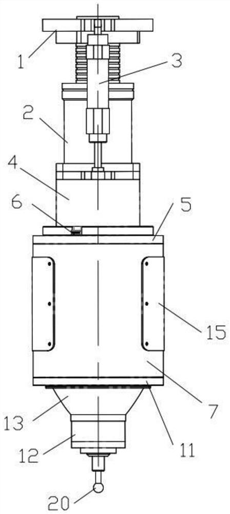
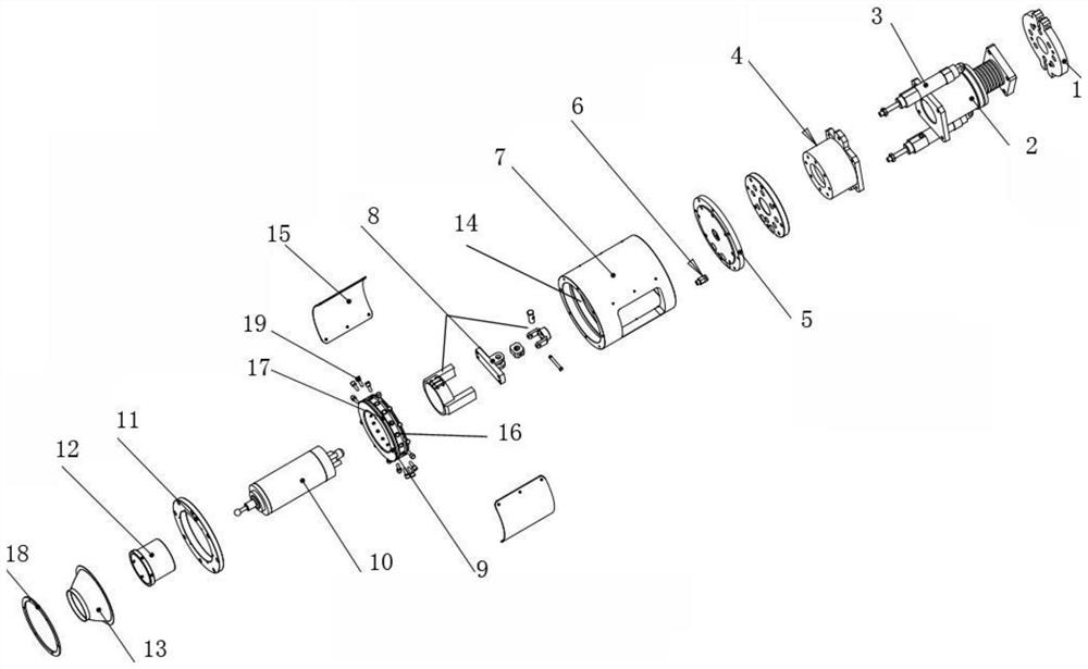
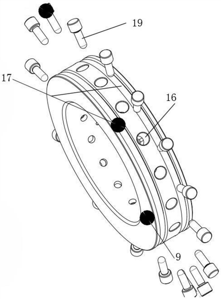
[0040] Such as Figure 1-Figure 3 As shown, a constant force grinding and polishing head mechanism includes a robot connecting flange 1, a linear motor 2, a balanced low-friction cylinder 3, a motor flange seat 4, a top connecting flange 5, an air source connecting head 6, and a housing 7. Universal joint assembly 8, radial constant force floating gas ring 9, spindle motor 10, front fixing flange 11, shaft sleeve 12, conical protective cover 13;

[0041] The top of the...


PUM


Abstract

The invention provides a constant-force grinding and polishing head mechanism, comprising a robot connecting flange, a linear motor, a balanced low-friction cylinder, a motor flange seat, a top connecting flange, an air source connecting head, a casing, a floating universal connecting seat, A radial constant force floating air ring, a spindle motor, and a front fixed flange; the bottom of the robot connecting flange is vertically connected to the linear motor, the two sides of the robot connecting flange are vertically connected to the balanced low-friction cylinder, and the bottom end of the balanced low-friction cylinder is connected to the motor flange A seat, the upper top surface of the motor flange seat is connected to the bottom of the linear motor; the bottom of the top connecting flange is connected to the outer shell; the inner wall of the inner cavity of the shell is provided with an annular installation groove; the annular installation groove is provided with a diameter There are several constant force pistons evenly distributed on the constant force floating air ring and the radial constant force floating air ring; the spindle motor runs through the radial constant force floating air ring, and one end of the constant force piston is attached to the outer wall of the spindle motor, and the main shaft The bottom of the motor is connected to the grinding head.

Description

technical field [0001] The invention belongs to the technical field of grinding and polishing equipment, and relates to a constant force grinding and polishing head mechanism. Background technique [0002] At present, most of the factory's grinding, polishing and deburring operations are mostly done by hand or using hand-held pneumatic or electric tools for grinding, grinding, filing, etc., which will easily lead to an increase in defective products, and the efficiency is low and the surface roughness of the processed products appears. unevenness etc. At the same time, high labor costs are required, and a small number of manufacturers have begun to use robots to install ordinary electric or pneumatic tools for automatic grinding. However, due to the irregularity of the rigid grinding and polishing surface of the mechanical arm, it is easy to damage the grinding tool or cause damage to the workpiece due to uneven force. In the above situation, the automatic constant force f...

Claims


Application Information

Patent Timeline
Patent Type & Authority Patents(China)
IPC IPC(8): B24B41/04B24B17/00B25J11/00
CPCB24B17/00B24B41/042B25J11/0065
Inventor 邹兆龙
Owner HUNAN JINGYI AUTOMATION
Why Eureka
Try Eureka