Insert piece of discharge tank in series type blast furnace
A technology of inserts and material tanks, applied in the direction of bell and funnel arrangement, etc., can solve the problems of particle size segregation, large impact force of material tank throttle valve, high speed, etc., to reduce impact wear, prolong service life, reduce pressure poor effect
- Summary
- Abstract
- Description
- Claims
- Application Information
AI Technical Summary
Problems solved by technology
Method used
Image
Examples
Embodiment 1
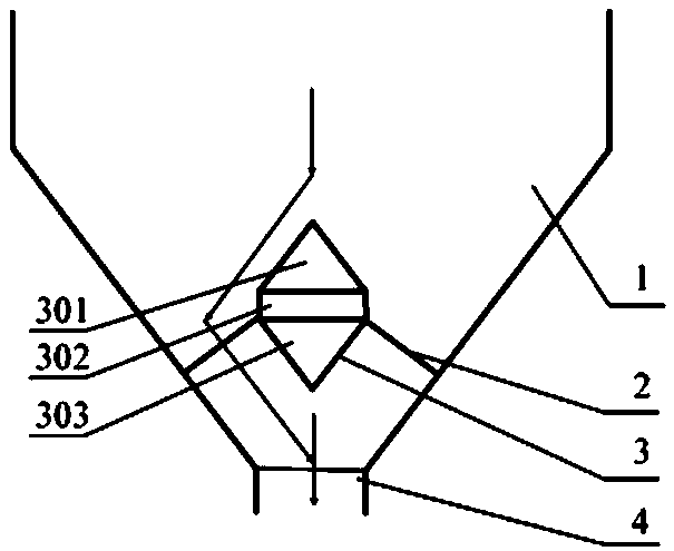
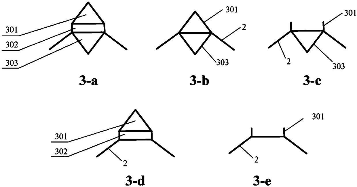
[0035] Example as image 3 As shown in -a, the insert body is sequentially divided into first part, second part and third part from top to bottom; the first part is an upper cone, the second part is a cylinder, and the third part It is a lower cone, and the first part, the second part and the third part are integrally formed or assembled.
Embodiment 2
[0036] Example two such as image 3 As shown in -c, the insert body consists of the first part and the third part from top to bottom; the first part is a circular tray, and the third part is a lower cone, which can block the part Large particles roll down to the empty space directly below the insert, reducing the proportion of large particles in the central area of the tank; the first and third parts are integrally formed or welded.
Embodiment 3
[0037] Embodiment three such as image 3As shown in -e, the insert body is only the first part; the first part is a circular tray, and the first part is integrally formed or welded with the support rod.
[0038] The above three are preferred embodiments. In fact, the combination of any two items in the first part, the second part, and the third part can improve the distribution of the charge to varying degrees, and the embodiments of the present invention can also adopt other combinations, such as image 3 -b, 3-d shown.
[0039] Process analysis of loading the charge into the feeding tank:
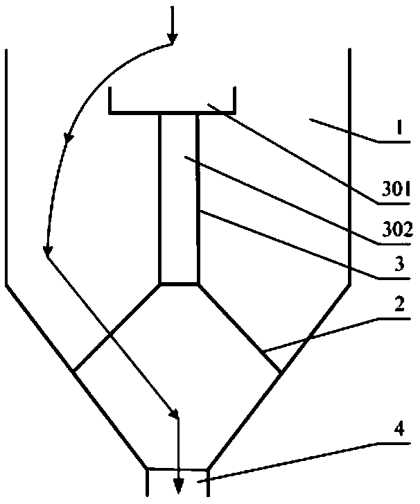
[0040] Such as Figure 4 As shown, the currently used insert is installed in the lower tank, just to protect the lower throttle valve from being hit by the charge. The tip is close to the wall, resulting in the shape of the charge in the lower tank with a low center and a high edge. The pile foot is located in the center of the tank, so that there are more large particles in the cente...
PUM
 Abstract
Description
Claims
Application Information
 - R&D
- Intellectual Property
- Life Sciences
- Materials
- Tech Scout
- Unparalleled Data Quality
- Higher Quality Content
- 60% Fewer Hallucinations
Browse by: Latest US Patents, China's latest patents, Technical Efficacy Thesaurus, Application Domain, Technology Topic, Popular Technical Reports.
© 2025 PatSnap. All rights reserved.Legal|Privacy policy|Modern Slavery Act Transparency Statement|Sitemap|About US| Contact US: help@patsnap.com


