Column laying device for spiral column

A technology of spiral columns and vertical columns, which is applied in the field of screw column laying equipment, can solve the problems of reducing work efficiency, prolonging the progress of the construction period, reducing the progress, etc., and achieves the effects of improving operation efficiency, reducing labor intensity, and good molding quality

Inactive Publication Date: 2019-02-12
盐城铭华国际货运代理有限公司
View PDF0 Cites 2 Cited by
  • Summary
  • Abstract
  • Description
  • Claims
  • Application Information

AI Technical Summary

Problems solved by technology

[0002] At present, when laying columns, some customers need to make some changes to the shape of the columns, not only to have the support effect of the columns, but also not just a straight up and down structure, and the spiral column is also the first choice for everyone, but, When laying spiral columns, it often requires experienced masters, long-term manual measurement and construction operations, which not only increases the difficulty of the operation, but also reduces work efficiency, and prolongs the progress of the construction period. Spiral columns are often operated based on their own operating experience, without certain operating standards, so that after the columns are built, they are often different, which requires subsequent trimming and processing, which is not conducive to the control of working hours and costs. reduction of

Method used

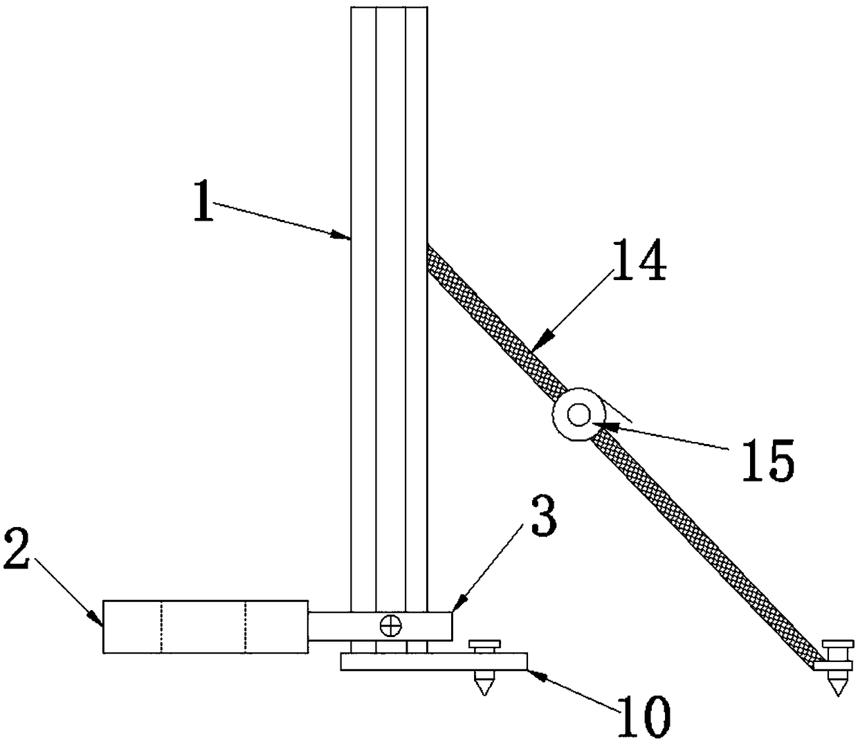
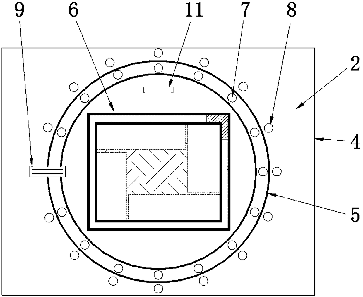
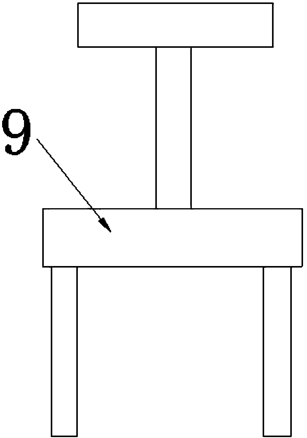

Image

  • Column laying device for spiral column
  • Column laying device for spiral column
  • Column laying device for spiral column

Examples


Embodiment Construction

[0020] It should be noted that, in the case of no conflict, the embodiments in the present application and the features in the embodiments can be combined with each other. The present invention will be described in detail below with reference to the accompanying drawings and examples.

[0021] It should be noted that the terminology used here is only for describing specific implementations, and is not intended to limit the exemplary implementations according to the present application. As used herein, unless the context clearly dictates otherwise, the singular is intended to include the plural, and it should also be understood that when the terms "comprising" and / or "comprising" are used in this specification, they mean There are features, steps, operations, means, components and / or combinations thereof.

[0022] It should be noted that the terms "first" and "second" in the description and claims of the present application and the above drawings are used to distinguish simila...


PUM


Abstract

The invention discloses a column laying device for a spiral column. The column laying device for the spiral column mainly comprises a column, wherein a gauge is further arranged, the column is connected with one end of the gauge through a sliding seat, the gauge is perpendicular to the column, and the sliding seat is used for sliding in the length direction of the column; the gauge comprises a frame body and a rotary disk arranged in the frame body, the rotary disk freely rotates in the frame body, the interior of the rotary disk is of a square hollow structure, and the rotary disk, the framebody and the square hollow are coaxially arranged; first connecting holes are formed in the surface of the rotary disk, and second connecting holes are formed in the surface of the frame body; a fixing frame is further arranged, the bottom of the fixing frame is of a U-shaped structure, the fixing frame is correspondingly connected with the first connecting holes and second connecting holes through the bottom of the fixing frame, and the rotary disk is fixed to the frame body. According to the column laying device for the spiral column, the structure is simple, the use is safe, labor intensityof an operator can be effectively reduced, the working efficiency can be improved, and the forming quality of the column is good.

Description

technical field [0001] The invention relates to the technical field of construction, in particular to a column-laying device for spiral columns. Background technique [0002] At present, when laying columns, some customers need to make some changes to the shape of the columns, not only to have the support effect of the columns, but also not just a straight up and down structure, and the spiral column is also the first choice for everyone, but, When laying spiral columns, it often requires experienced masters, long-term manual measurement and construction operations, which not only increases the difficulty of the operation, but also reduces work efficiency, and prolongs the progress of the construction period. Spiral columns are often operated based on their own operating experience, without certain operating standards, so that after the columns are built, they are often different, which requires subsequent trimming and processing, which is not conducive to the control of wor...

Claims


Application Information

Patent Timeline
Patent Type & Authority Applications(China)
IPC IPC(8): E04G21/16E04G21/18
CPCE04G21/16E04G21/1841
Inventor 陈明忠
Owner 盐城铭华国际货运代理有限公司
Why Eureka
Try Eureka