
Slide ring seal arrangement of a hydrodynamic retarder, and hydrodynamic retarder

A mechanical seal device and hydraulic reducer technology, applied in the field of hydraulic reducer, can solve the problems of mechanical seal damage, lack of lubricating medium, failure, etc., and achieve the effect of long service life

Inactive Publication Date: 2019-02-12
CARL FREUDENBERG KG +1
View PDF5 Cites 2 Cited by
  • Summary
  • Abstract
  • Description
  • Claims
  • Application Information

AI Technical Summary

Problems solved by technology

The problem that arises here is that, when the retarder is not in operation, that is, when there is no liquid in the retarder chamber and the vehicle has not braked for a relatively long period of time, for example, there is not enough pressure on the mechanical seal. Lubricating medium supplied by liquid
This can lead to so-called dry running of the mechanical seal, which leads to excessive heat generation at the mechanical seal and, in extreme cases, to damage or failure of the mechanical seal

Method used


Image

  • Slide ring seal arrangement of a hydrodynamic retarder, and hydrodynamic retarder
  • Slide ring seal arrangement of a hydrodynamic retarder, and hydrodynamic retarder
  • Slide ring seal arrangement of a hydrodynamic retarder, and hydrodynamic retarder

Examples


Embodiment Construction

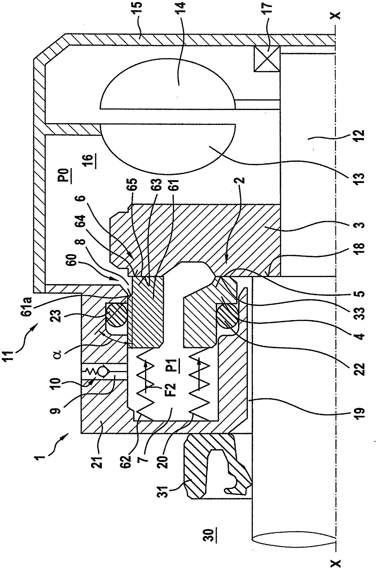
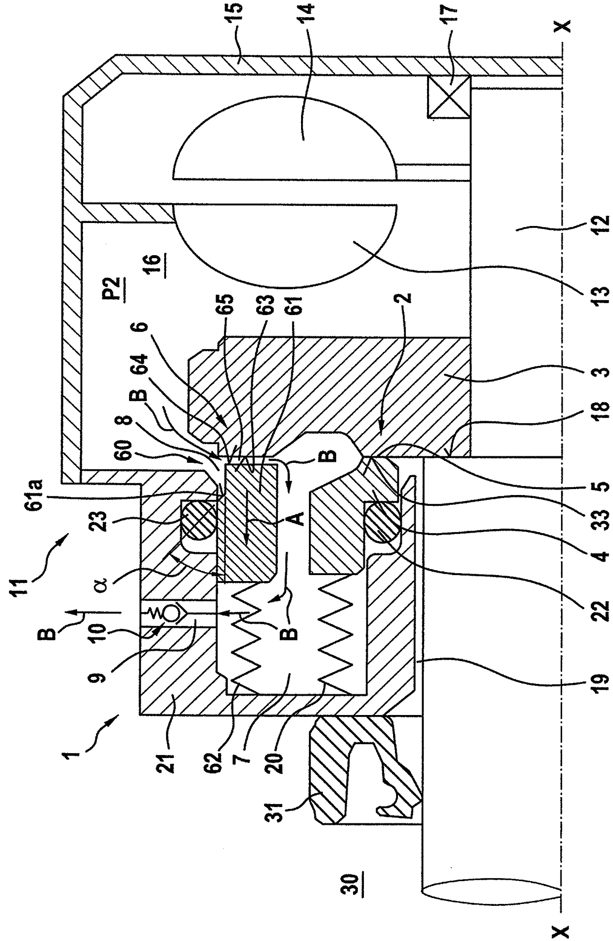
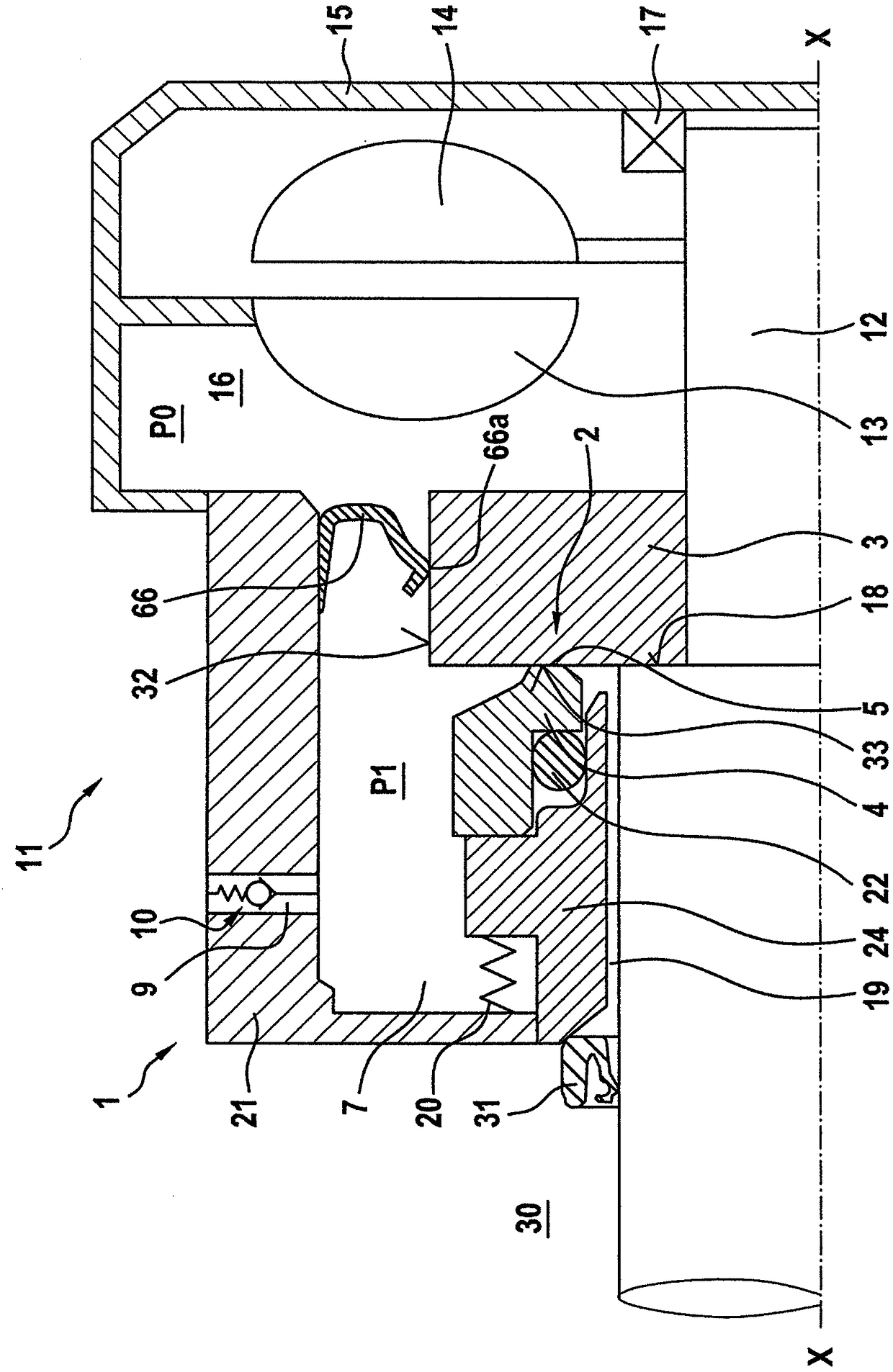
[0069] Refer to the following figure 1 and figure 2 The mechanical seal device 1 and the hydraulic retarder 11 according to the first preferred embodiment of the present invention will be described in detail.

[0070] figure 1 A sectional view of a reducer 11 is shown, comprising a reducer shaft 12 , a stator 13 , a rotor 14 and a reducer housing 15 . The gear unit housing 15 encloses a gear unit working chamber 16 . The stator 13 is fastened here to the gear unit housing 15 . The rotor 14 is connected to the reducer shaft 12 . Reference numeral 17 denotes a bearing (cantilever support) on which the reducer shaft 12 is mounted.

[0071] Hydrodynamic retarders are used, for example, in vehicles, especially for vehicles such as trucks or buses. Here, the braking work of the retarder is performed by filling the retarder working chamber 16 with liquid (for example oil), ie converted into heat. After a successful braking operation, the fluid is then drained from the retarde...


PUM


Abstract

The invention relates to a mechanical seal arrangement, in particular a retarder-mechanical seal arrangement, comprising a first mechanical seal with a first rotating slide ring and a first stationaryslide ring which define a first sealing gap in between them, an additional seal, a cooling medium space which is filled with a cooling medium and extends all the way to the sealing gap of the first mechanical seal, wherein the first mechanical seal seals the cooling medium space against an environment, a cooling medium access into the cooling medium space for supplying cooling medium, and a cooling medium exit from the cooling medium space for draining cooling medium, wherein the additional seal is arranged in the cooling medium access, and wherein the additional seal is configured to open when a pressure inside the cooling medium access rises above a first pressure inside the cooling medium space, and to close at a second pressure inside the cooling medium access that is lower than the first pressure inside the cooling medium space.

Description

technical field [0001] The invention relates to a mechanical seal device of a hydraulic reducer and a hydraulic reducer with the mechanical seal device. Background technique [0002] Hydrodynamic retarders are used in the drives of vehicles, especially for vehicles such as trucks or buses. In this case, the gear unit is activated or deactivated by filling and emptying the gear unit working chamber, in which the stator and the rotor connected to the gear unit shaft are arranged. The working medium is liquid, usually oil or water. The retarder is usually used for vehicle braking. To seal the gear unit against the environment, mechanical seals can be used, for example. The problem that arises here is that, when the retarder is not in operation, that is, when there is no liquid in the retarder chamber and the vehicle has not braked for a relatively long period of time, for example, there is not enough pressure on the mechanical seal. The lubricating medium supplied by the li...

Claims


Application Information

Patent Timeline
Patent Type & Authority Applications(China)
IPC IPC(8): F16J15/34F16D57/04B60T10/02B60T1/087
CPCB60T1/087B60T10/02F16D57/04F16J15/3404F16J15/3452F16J15/3464F16J15/006F16D2125/08F16D57/00
Inventor C·西蒙U·布劳恩K·朗
Owner CARL FREUDENBERG KG
Learn More