Broadband end-fire antenna on basis of surface wave waveguide and high-impedance surfaces

A high-impedance surface and end-fire antenna technology, which is applied in the direction of separately powered antenna array, antenna grounding device, antenna grounding switch structure connection, etc., can solve the problems of high antenna design complexity, obstacles to broadband implementation, etc., and achieve good radiation buff effect

Active Publication Date: 2019-02-12
SOUTHWEST JIAOTONG UNIV
View PDF2 Cites 6 Cited by
  • Summary
  • Abstract
  • Description
  • Claims
  • Application Information

AI Technical Summary

Problems solved by technology

However, the high design complexity and wideband implementation of this antenna have become obstacles in its practical application

Method used


Image

  • Broadband end-fire antenna on basis of surface wave waveguide and high-impedance surfaces
  • Broadband end-fire antenna on basis of surface wave waveguide and high-impedance surfaces
  • Broadband end-fire antenna on basis of surface wave waveguide and high-impedance surfaces

Examples


Embodiment Construction

[0030] The technical scheme of the present invention is described in further detail below in conjunction with specific embodiment and accompanying drawing, but protection scope of the present invention is not limited to the following description.

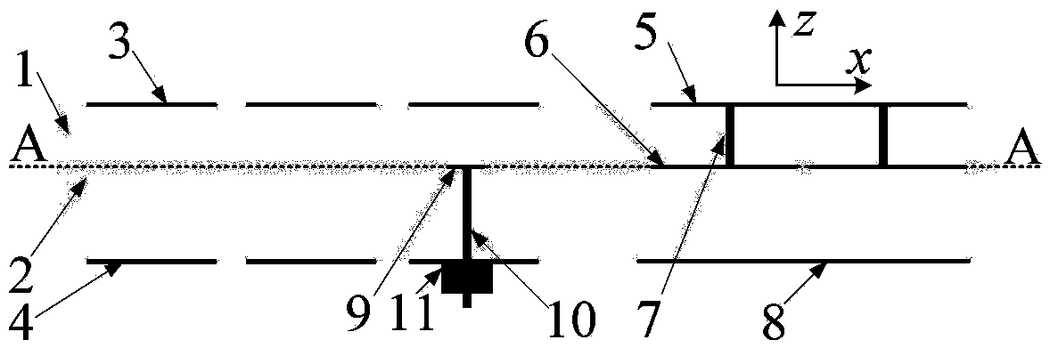
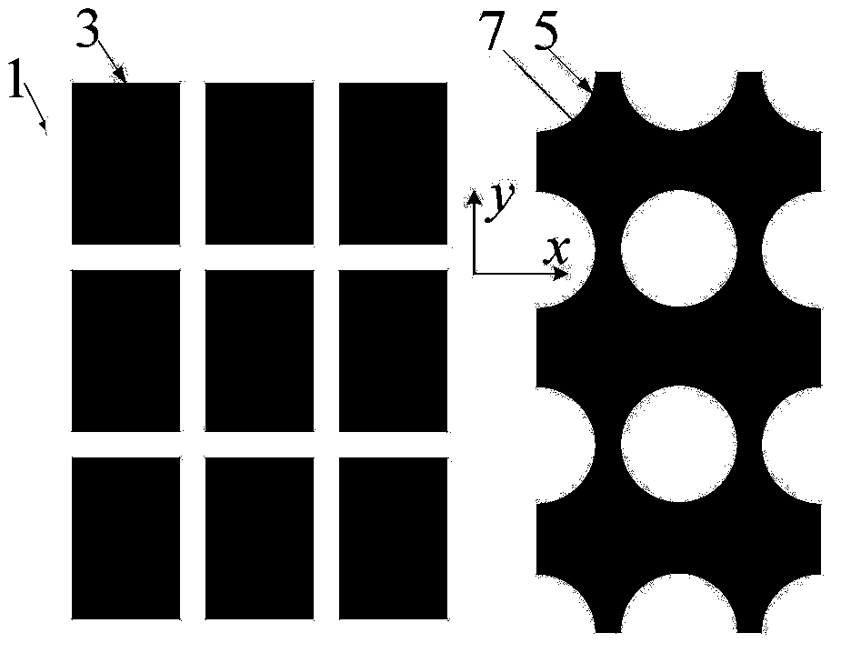
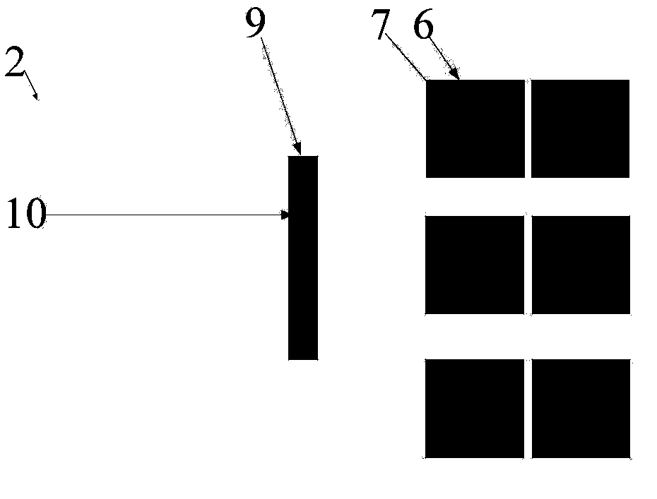
[0031] This embodiment provides a broadband end-fire planar antenna based on surface wave guides and high-impedance surfaces, and its side view is as follows figure 1As shown, a wide impedance bandwidth can be achieved while ensuring good far-field end-fire performance (the relative bandwidth of the center is 33.5%), including the first dielectric substrate 1, the second dielectric substrate 2, the surface wave waveguide part, the high impedance The surface part and the surface wave exciter part, the first dielectric substrate 1 is arranged above the second dielectric substrate 2, the surface wave waveguide part includes an upper rectangular patch array 3 and a lower rectangular patch array 4, the upper layer The rectangular patch a...


PUM


Abstract

The invention relates to the technical field of microwave antennas, in particular to a broadband end-fire antenna on the basis of surface wave waveguide and high-impedance surfaces. The broadband end-fire antenna comprises a first dielectric substrate, a second dielectric substrate, a surface wave waveguide portion, a high-impedance surface portion and a surface wave exciter portion. The broadbandend-fire antenna which is a panel end-fire antenna has the advantages that end-fire effects can be realized by surface wave conduction and suppression functions of the surface wave waveguide and thehigh-impedance surfaces, and the broadband end-fire antenna is excellent in characteristics such as radiation gain, front-to-back ratio and gain flatness; two resonant modes in the surface wave waveguide can be excited, the high-impedance surfaces with the broad stop band characteristics are adopted, accordingly, the broadband end-fire antenna has a broadband function, and the relative central bandwidths can reach 33.5%; the panel antenna has the end-fire radiation performance and broad impedance bandwidth functions, and is simple in structure and easy to implement and integrate, and the performance of the antenna can be effectively enhanced when the broadband end-fire antenna is applied to radar, communication, remote sensing and measuring, electronic countermeasures and the like.

Description

technical field [0001] The invention relates to the technical field of microwave antennas, in particular to a broadband end-fire antenna based on surface wave guides and high-impedance surfaces. Background technique [0002] Due to the advantages of strong directivity and high gain, flat-panel end-fire antennas have shown good performance and played an important role in contemporary military and civilian applications. Traditional flat-panel end-fire antennas mainly include flat-panel dipole arrays, Yagi dipole arrays, log-periodic dipole arrays, Vivaldi antennas, and other designs. These designs are either because of their narrow impedance bandwidth or because of their The flatness of the radiation gain within the bandwidth is poor, and it is often subject to many restrictions in practical applications. Therefore, widening the impedance bandwidth of the antenna and ensuring the flatness of the gain within the bandwidth is a difficult point in the research and design of the ...

Claims


Application Information

Patent Timeline
Patent Type & Authority Applications(China)
IPC IPC(8): H01Q1/38H01Q1/48H01Q1/50H01Q21/06
Inventor 程友峰丁霄廖成
Owner SOUTHWEST JIAOTONG UNIV
Why Eureka
Try Eureka