
Hair observation device with magnifying glass

A technology of observation device and magnifying glass, which is applied in diagnostic recording/measurement, medical science, sensors, etc., can solve the problems of costing a lot of money and time, wasting money and time, etc., and achieves low cost, easy to grasp and use, and convenient to use Effect

Pending Publication Date: 2019-02-15
浙江自贸区费米善科技发展有限公司
View PDF5 Cites 0 Cited by
  • Summary
  • Abstract
  • Description
  • Claims
  • Application Information

AI Technical Summary

Problems solved by technology

At present, the systematic detection and maintenance of hair can be completed in beauty parlors or medical institutions, but it takes a lot of money and time. Before taking systematic maintenance measures, if people can predict the maintenance in the early stage, they can determine whether it is necessary System maintenance provides a favorable basis to avoid wasting money and time
At present, there is no effective tool that can observe the state of hair roots and scalp by itself. People can only observe the surface by visual inspection.

Method used


Image

  • Hair observation device with magnifying glass
  • Hair observation device with magnifying glass
  • Hair observation device with magnifying glass

Examples


Embodiment 1

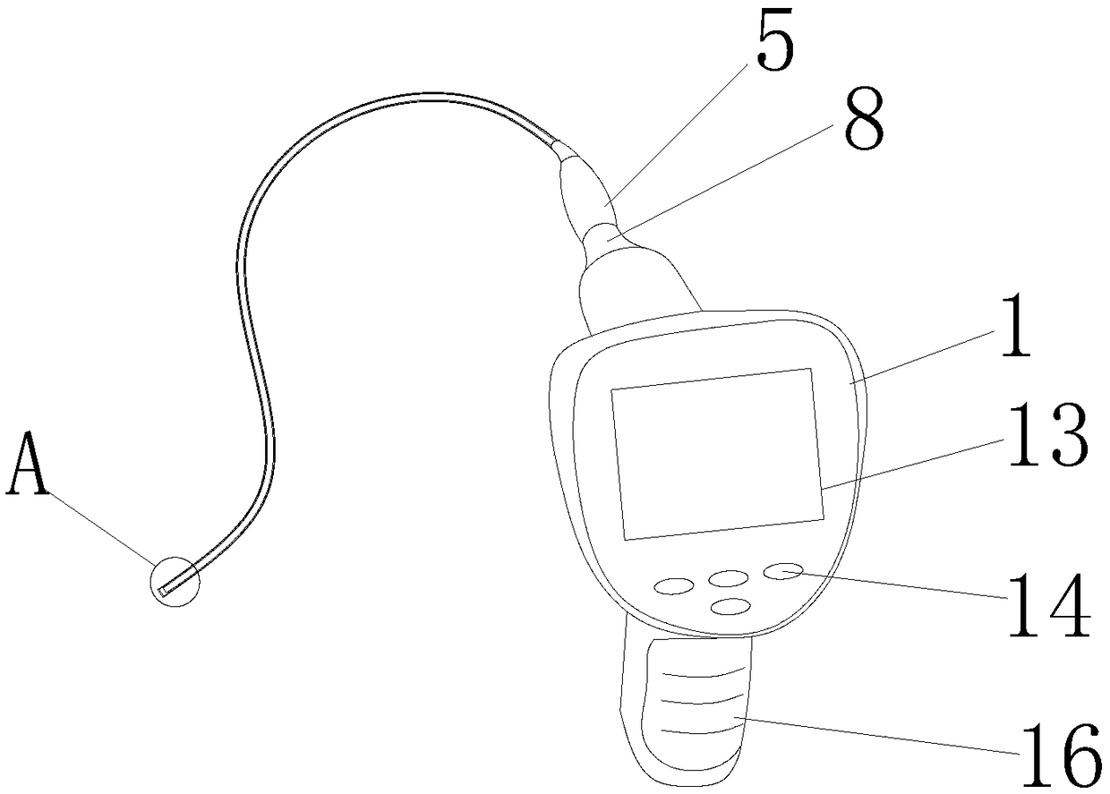
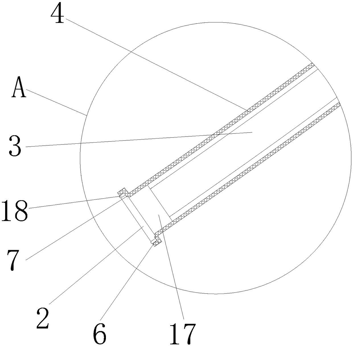
[0022] Embodiment 1 of the present invention: a hairline observation device with a magnifying glass, comprising an observation case 1, a magnifying lens 2 and an optical fiber wire 3, and the optical fiber wire 3 is arranged in a hollow cavity of a linear insulating sleeve 4 with a length of 10 cm , one end of the linear insulating sleeve 4 is provided with a connection port 5, the other end of the linear insulating sleeve 4 is provided with a circular port 6, the magnifying lens 2 is arranged on the circular port 6, and the observation shell 1 is provided with a connector 8 configured with the connection port 5 . A CCD image receiver 17 is arranged between the magnifying lens 2 and the optical fiber guide 3 .

Embodiment 2

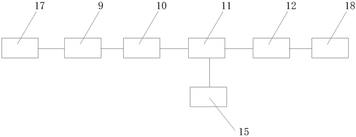
[0023] Embodiment 2 of the present invention: a hairline observation device with a magnifying glass, comprising an observation case 1, a magnifying lens 2 and an optical fiber wire 3, and the optical fiber wire 3 is arranged in a hollow cavity of a linear insulating sleeve 4 with a length of 20 cm , one end of the linear insulating sleeve 4 is provided with a connection port 5, the other end of the linear insulating sleeve 4 is provided with a circular port 6, the magnifying lens 2 is arranged on the circular port 6, and the observation shell 1 is provided with a connector 8 configured with the connection port 5 . A CCD image receiver 17 is arranged between the magnifying lens 2 and the optical fiber guide 3 . The magnifying lens 2 is provided with an annular end face 7 , and the annular end face 7 is fitted on the end face of the circular port 6 . Further, it also includes a data receiver 9, a converter 10, a processor 11 and a display 12, the optical fiber wire 3 is connect...

Embodiment 3

[0024] Embodiment 3 of the present invention: a hairline observation device with a magnifying glass, comprising an observation case 1, a magnifying lens 2 and an optical fiber wire 3, the optical fiber wire 3 is arranged in the hollow cavity of a linear insulating sleeve 4, and the linear One end of the insulating sleeve 4 is provided with a connection port 5, the other end of the linear insulating sleeve 4 is provided with a circular port 6, the magnifying lens 2 is arranged on the circular port 6, and the observation shell 1 is provided with a Connect the connector 8 of the port 5-phase configuration. A CCD image receiver 17 is arranged between the magnifying lens 2 and the optical fiber guide 3 . The magnifying lens 2 is provided with an annular end face 7 , and the annular end face 7 is fitted on the end face of the circular port 6 . Further, it also includes a data receiver 9, a converter 10, a processor 11 and a display 12, the optical fiber wire 3 is connected to the d...


PUM


Abstract

The invention discloses a hair observation device with a magnifying glass, comprising an observation casing, a magnifying glass, and a fiber optic wire. The fiber optic wire is arranged in a middle cavity of a linear insulating sleeve, wherein one end of the linear insulating sleeve is provided with a connecting port. The other end of the linear insulating sleeve is provided with a circular port,wherein the magnifying glass is arranged on the circular port. The observation casing is provided with a connecting head configured with the connecting port. The hair observation device is convenientfor people to observe their hair roots and scalp state by placing the magnifying glass over the scalp with a long enough linear insulating sleeve provided. A data receiver, a processor, a converter, amonitor and a controller are all integrated into the small observation casing with a handle provided to make the hair observation device easy for self-using. The cost is low. Through the monitor, theuser can observe his hair and scalp state in real time.

Description

technical field [0001] The invention relates to an observation device, in particular to a hair observation device with a magnifying glass. Background technique [0002] With the increasing pressure of life, problems such as greasy hair, dandruff, itchy scalp, and hair loss emerge in an endless stream among the population, and the proportion of people suffering from hair quality is as high as two-thirds. At present, the systematic detection and maintenance of hair can be completed in beauty parlors or medical institutions, but it takes a lot of money and time. Before taking systematic maintenance measures, if people can predict the maintenance in the early stage, they can determine whether it is necessary System maintenance provides a favorable basis to avoid wasting money and time. At present, there is no effective tool that can observe the state of hair roots and scalp by itself, and people can only observe the surface by visual inspection. Contents of the invention [...

Claims


Application Information

Patent Timeline
Patent Type & Authority Applications(China)
IPC IPC(8): A61B5/00
CPCA61B5/0077
Inventor 戴博松童舟赵海英邓隆隆
Owner 浙江自贸区费米善科技发展有限公司
Learn More