Linkage-type prosthetic hand

A prosthetic hand and linkage technology, applied in the field of bionic hands, can solve the problems of poor anti-reversal ability, low clamping force, complex structure, etc., and achieve the effect of strong support, anti-reversal, and avoid cumbersome structures

Pending Publication Date: 2019-02-15
INST OF AUTOMATION CHINESE ACAD OF SCI +1
View PDF6 Cites 2 Cited by
  • Summary
  • Abstract
  • Description
  • Claims
  • Application Information

AI Technical Summary

Problems solved by technology

[0003] Chinese patent document CN 106821560A discloses a two-way gear transmission prosthetic hand, which includes a fixed part and a movable part. The fixed part includes a connection end and a palm end. The movable part includes two sets of symmetrically arranged artificial fingers. The components include a drive motor and a main gear. The center of the main gear is extended along the horizontal direction to form a gear shaft. The gear shaft meshes with the first arc-shaped gear, and a reversing gear is provided between the gear shaft and the second arc-shaped gear. The entire prosthetic hand needs to be equipped with multiple gears to realize the opening and closing movement of the thumb and other fingers, and the structure is complex
[0004] The opening and closing methods of the existing prosthetic hands basically adopt the gear-driven opening and closing method under electric control. Through the direct gear transmission of the thumb and the passive rotation of other fingers, the object can be clamped. Its clamping force is low, and its anti-rotation ability is poor when the prosthetic hand grabs objects

Method used


Image

  • Linkage-type prosthetic hand
  • Linkage-type prosthetic hand
  • Linkage-type prosthetic hand

Examples


Embodiment Construction

[0037] The technical solutions of the present invention will be clearly and completely described below in conjunction with the accompanying drawings. Apparently, the described embodiments are some of the embodiments of the present invention, but not all of them. Based on the embodiments of the present invention, all other embodiments obtained by persons of ordinary skill in the art without making creative efforts belong to the protection scope of the present invention.

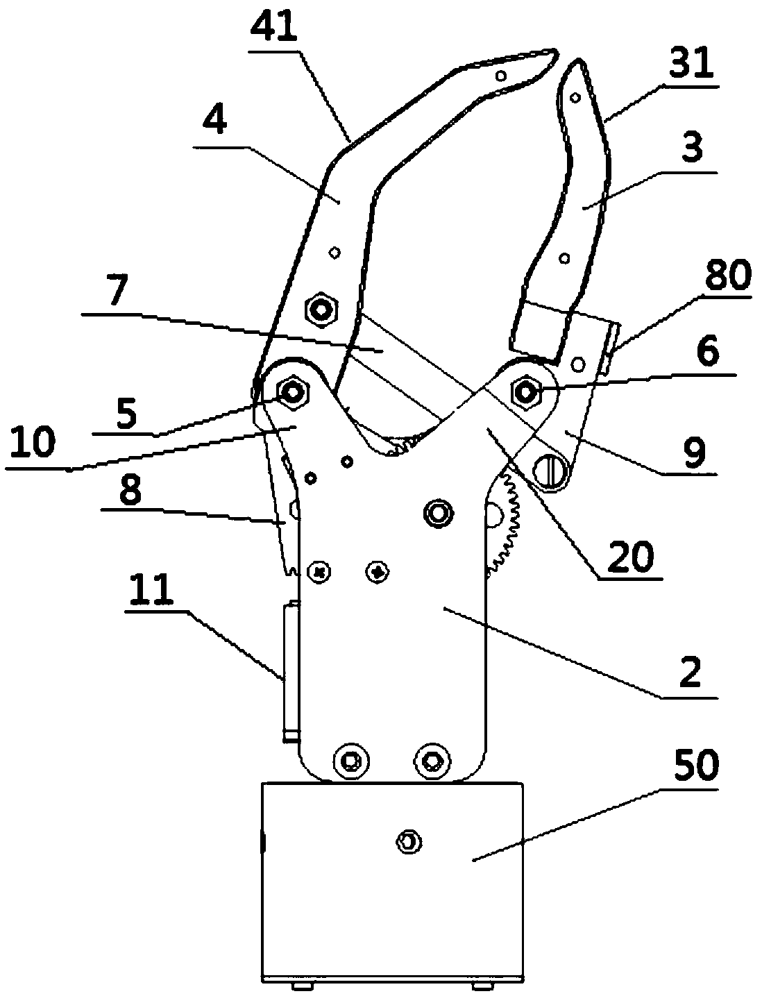
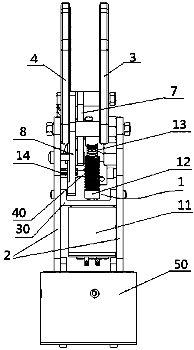
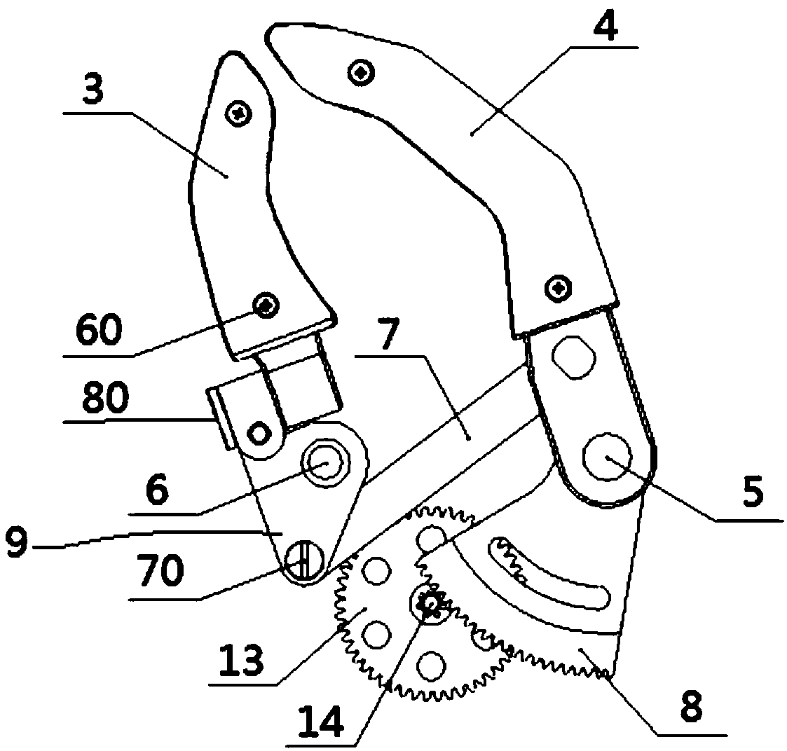
[0038] Such as figure 1 and figure 2 As shown, the present invention provides a linkage prosthetic hand, comprising a rotating wrist 50, a gear drive device 1, two support plates 2, a thumb 3 positioned above the two support plates 2 and a finger 4 kneaded with the thumb 3, and two support plates 2 is vertically arranged on the rotating wrist 50, the fingers 4 form a relative rotation connection with the two support plates 2 through the first rotating shaft 5 arranged between the two support plates 2, and th...


PUM


Abstract

The invention discloses a linkage-type prosthetic hand. The prosthetic hand comprises a gear driving device, two supporting plates, a thumb and a finger pinched with the thumb; the finger is in relative rotational connection with the two supporting plates through a first rotating shaft disposed between the two supporting plates, the thumb is in relative rotational connection with the two supporting plates through a second rotating shaft disposed between the two supporting plates, and a connecting rod is disposed between the thumb and the finger; a driving gear is disposed at the lower end of the thumb or the finger, and the gear driving device is in driving connection with the driving gear; the gear driving device drives the driving gear to rotate, and the driving gear drives the finger orthe thumb to rotate around the corresponding first rotating shaft or the corresponding second rotating shaft, so that the other end of the connecting rod drives the thumb or the finger to rotate around the corresponding second rotating shaft or the corresponding first rotating shaft in the opposite direction. The finger and the thumb are connected and disconnected under the joint action of the gear driving device and the connecting rod, the structure is simple, and adoption of a cumbersome structure of a reversing gear is avoided.

Description

technical field [0001] The invention relates to the technical field of bionic hands, in particular to a linked prosthetic hand. Background technique [0002] Myoelectric prosthetic hands can replace missing limbs and provide convenience for the daily life of disabled patients with missing upper limbs. It is one of the important research directions in the field of rehabilitation engineering. [0003] Chinese patent document CN 106821560A discloses a two-way gear transmission prosthetic hand, which includes a fixed part and a movable part. The fixed part includes a connection end and a palm end. The movable part includes two sets of symmetrically arranged artificial fingers. The components include a drive motor and a main gear. The center of the main gear is extended along the horizontal direction to form a gear shaft. The gear shaft meshes with the first arc-shaped gear, and a reversing gear is provided between the gear shaft and the second arc-shaped gear. The entire prosth...

Claims


Application Information

Patent Timeline
Patent Type & Authority Applications(China)
IPC IPC(8): A61F2/58A61F2/72
CPCA61F2/583A61F2/586A61F2/72
Inventor 朱金营易建强胡宾宾李加良
Owner INST OF AUTOMATION CHINESE ACAD OF SCI
Why Eureka
Try Eureka