Pin lifting device

A technology of a pin and a lifting device, which is applied in the field of tooling equipment, can solve the problem that a pin with a larger diameter or a pin and a pin hole cannot be effectively removed, and achieves the effect of simple structure, high efficiency and avoiding device scrapping.

Active Publication Date: 2019-02-15
JILIN TEACHERS INST OF ENG & TECH
View PDF5 Cites 8 Cited by
  • Summary
  • Abstract
  • Description
  • Claims
  • Application Information

AI Technical Summary

Problems solved by technology

[0006] The invention provides a pin removal device, which can solve the problem that the prior art cannot effectively remove the pin with a larger diameter or when corrosion occurs between the pin and the pin hole to generate greater resistance

Method used


Image

  • Pin lifting device
  • Pin lifting device
  • Pin lifting device

Examples


Embodiment 1

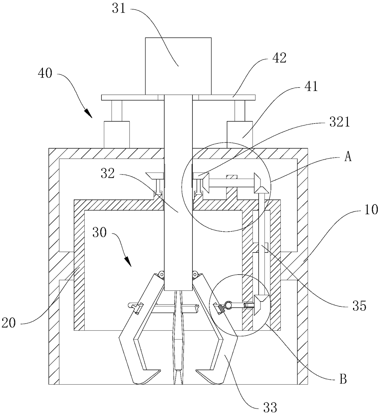
[0034] Such as figure 1 As shown, a pin removing device provided in an embodiment of the present invention includes:

[0035] The outer casing 10 is a barrel-shaped structure with a columnar bottom and an opening, and has a storage cavity;

[0036]The lifting device 40 includes a lifting shaft 32 and a lifting device. The lifting device is arranged on the outer casing 10 to drive the lifting shaft 32 to move up and down. The outer casing 10 is provided with a storage hole for accommodating the lifting The shaft 32 passes through, and the lifting device 40 is an electric telescopic rod 41 or a cylinder. The electric telescopic rod 41 is used as an example in this embodiment. A lifting plate 42 is connected to the upper end of the electric telescopic rod 41, and the lifting shaft 32 is connected to the mounting plate. When the rod 41 drives the lifting plate 42 to move, it drives the lifting shaft 32 to move up and down;

[0037] The grabbing device includes several grabbing c...

Embodiment 2

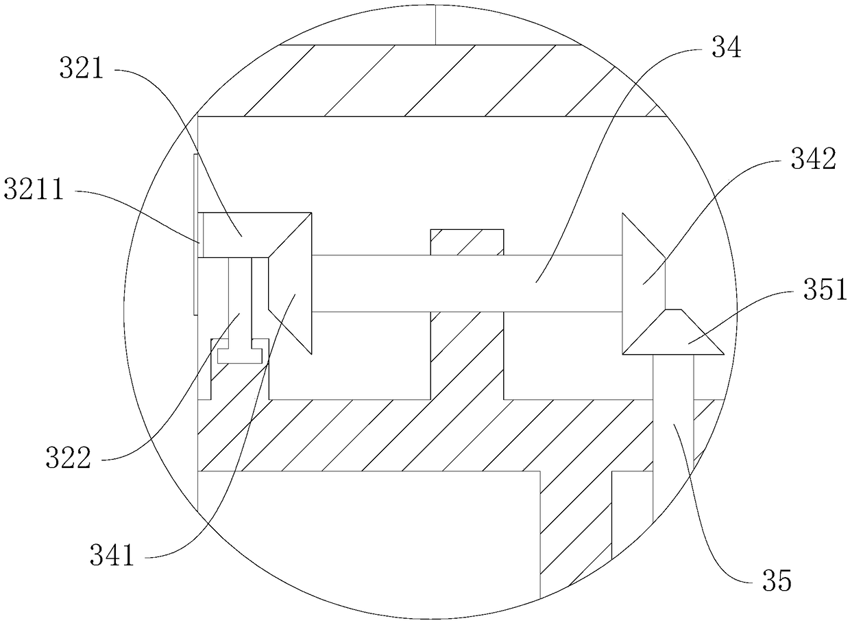
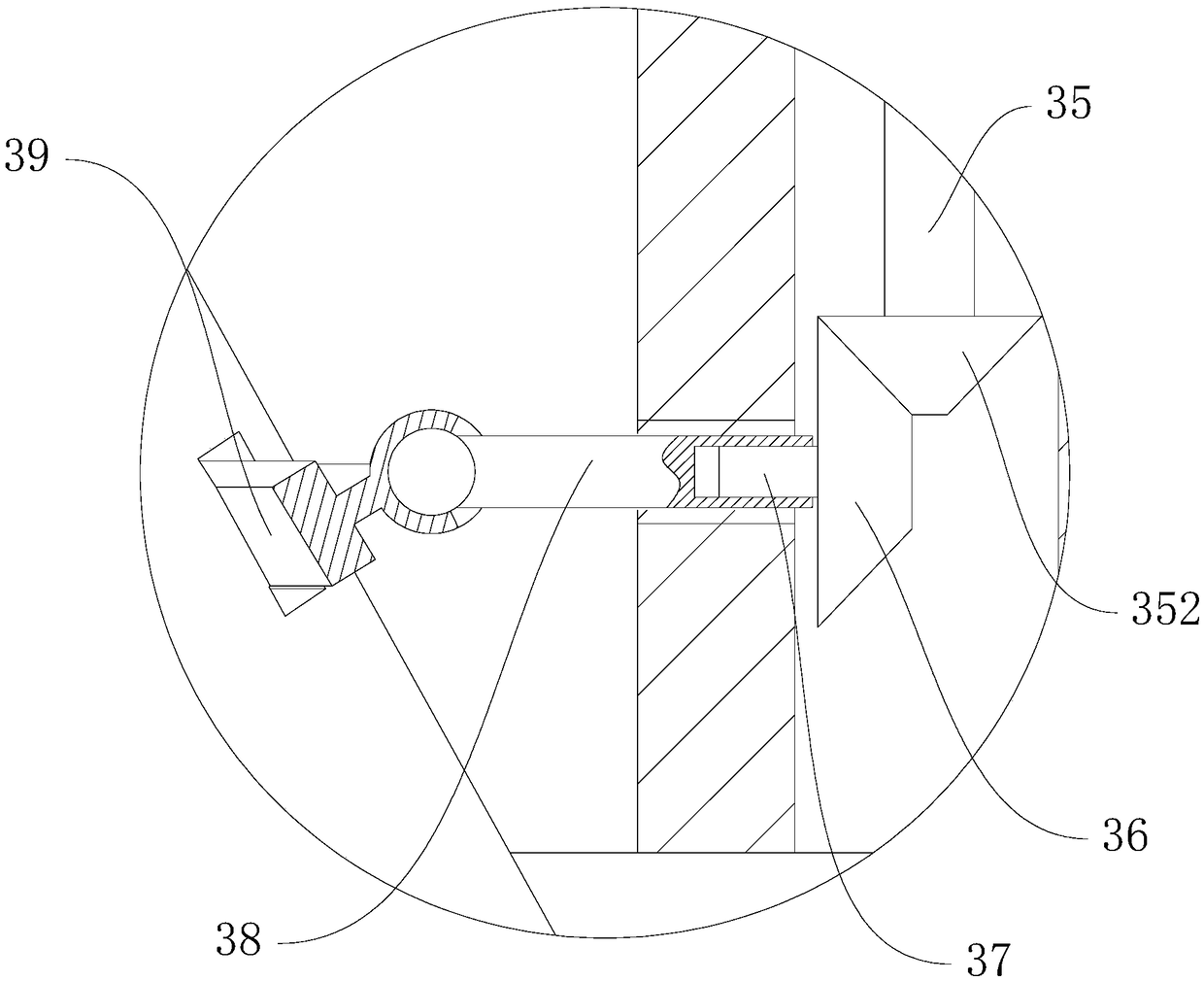
[0039] On the basis of Example 1, as Figure 1-6 As shown, because some pins are affected by the environment of the use occasion, such as rust or a relatively large interference, resulting in a relatively large force between the pin and the pin hole, at this time only rely on the friction between the grasping claw 33 and the pin It is still difficult to pull out the pin, so this embodiment also includes a grinding device 30 and an inner casing 20, the inner casing 20 is fixedly arranged in the outer casing 10, and there is a gap between the inner casing 20 and the outer casing 10. A certain gap, the peripheral side of the inner casing 20 is fixedly connected by a fixed block, such as figure 1 As shown, the grinding device 30 includes a motor 31, a driving bevel gear 321, a first connecting shaft 34, a second connecting shaft 35, a pushing connecting rod 38, a pushing spline shaft 37 and several driving rings 39, the hook portion A cutter 331 is provided, and the cutter 331 ca...

Embodiment 3

[0042] In another embodiment, in order to prevent the motor 31 from being directly lifted, the pulling force of the lifting shaft 32 on the main shaft of the motor 31 will cause damage to the motor 31. Therefore, as Figure 7 and Figure 8 As shown, the outer casing 10 is provided with a support arm 44, and the lifting shaft 32 is provided with a lifting plate 42, and the lifting plate 42 and the lifting device can be arranged along the axis perpendicular to the lifting shaft 32. Relative rotation in the plane, the two sides of the motor 31 are provided with a support slide bar 45, one end of the support slide bar 45 is fixedly connected to the motor 31, and the other end can be moved up and down along the extension direction of the lifting shaft 32 Slidably arranged on the support arm 44 .

[0043] Specifically, the lifting plate 42 is provided with an annular chute coaxial with the lifting shaft 32, and the output end of the lifting device is provided with a lifting slider ...


PUM


Abstract

The invention discloses a pin lifting device and belongs to the field of tool equipment. The device comprises a shell, a hoisting device and a grabbing device, wherein the shell is provided with a containing cavity; the hoisting device comprises a hoisting shaft and a lifting device which is arranged on the shell and used for driving the hoisting shaft to move up and down; the grabbing device comprises a plurality of grabbing claws uniformly arranged in the circumferential direction of the hoisting shaft, and the grabbing claws are of a V-shaped structure as a whole; one end of each grabbing claw is hinged to the lower end of the hoisting shaft, and the other end of each grabbing claw is provided with a hook portion protruding inwards; and the hook portions are obliquely arranged upwards.The pin lifting device can achieve hoisting by means of electric power or pneumatically, and the problem that a thread is used for driving for lifting for long-time use, the thread is abraded easily and consequently the device is scraped can be solved while the work efficiency is improved and the manpower is lowered; and self adaption to the external force borne by a pin is achieved, the problem that when the external force borne by the pin is large, the grabbing claws and the pin fall off easily is solved, the structure is simple, direct clamping hoisting is achieved, operation is convenient,and single-person operation can be achieved.

Description

technical field [0001] The invention relates to the field of tooling equipment, in particular to a pin removing device. Background technique [0002] In the field of machinery, pins are widely used in various molds and equipment, and can play the role of positioning or connection. Cylindrical pins are commonly used pins, which are mostly installed on parts through interference fit. Cylindrical pins can be divided into It is a cylindrical pin with a threaded hole and a cylindrical pin without a threaded hole. The cylindrical pin with a threaded hole can be removed with a bolt suitable for the threaded hole. For the cylindrical pin without a threaded hole, due to the The installation hole of the pin is different, and its disassembly method is also different. On different parts, due to the design requirements, the installation hole of the cylindrical pin has two types: through hole and blind hole. For the through hole type installation hole, it can be used The punch punches ou...

Claims


Application Information

Patent Timeline
Patent Type & Authority Applications(China)
IPC IPC(8): B23P19/02
CPCB23P19/02
Inventor 王鹏鲍艳王艳萍郑作涛
Owner JILIN TEACHERS INST OF ENG & TECH
Why Eureka
Try Eureka