Upper mounting type ball valve mounting and dismantling device

A technology of dismantling device and ball valve, which is applied to valve device, cock including cut-off device, mechanical equipment, etc., can solve the problems of small matching gap between valve seat and valve cavity, valve seat being easily stuck, and high friction force, etc. The piston action process is stable, easy to disassemble and carry, and the disassembly speed is fast.

Pending Publication Date: 2019-02-15
ZHEJIANG OFILM PETROLEUM EQUIP CO LTD
View PDF0 Cites 0 Cited by
  • Summary
  • Abstract
  • Description
  • Claims
  • Application Information

AI Technical Summary

Problems solved by technology

[0003] The top-entry ball valve for pipelines generally has a large diameter. Due to the small space in the inner cavity, the gap between the valve seat and the valve cavity is small and the friction is large. After the product is used for a certain period of time, the valve cavity is corroded and the valve seat is easily stuck. On-site maintenance and disassembly Both the seat and the ball are very difficult, and a tool for quick disassembly and installation is urgently needed

Method used


Image

  • Upper mounting type ball valve mounting and dismantling device
  • Upper mounting type ball valve mounting and dismantling device
  • Upper mounting type ball valve mounting and dismantling device

Examples


Embodiment Construction

[0020] Embodiments of the present invention are described in detail below, examples of which are shown in the drawings, wherein the same or similar reference numerals designate the same or similar elements or elements having the same or similar functions throughout. The embodiments described below by referring to the figures are exemplary and are intended to explain the present invention and should not be construed as limiting the present invention.

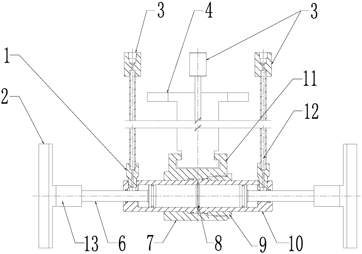
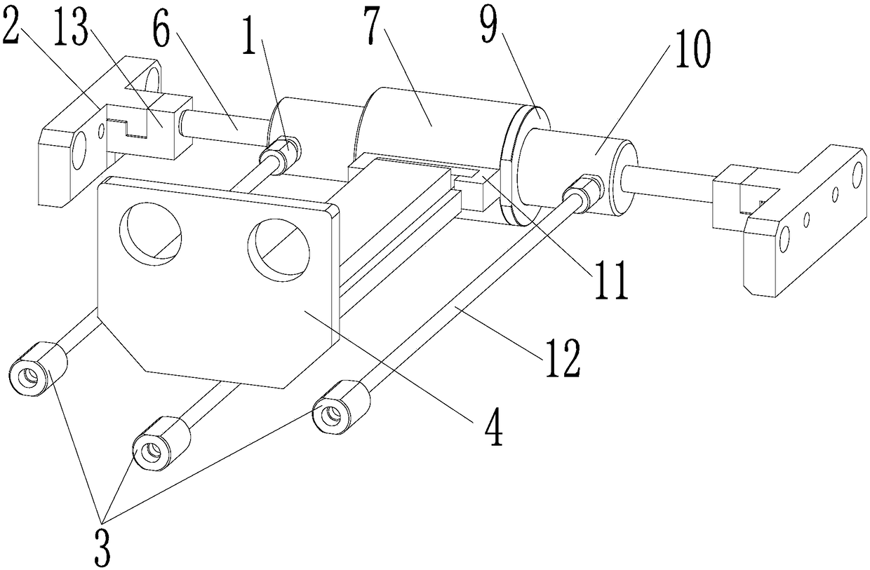
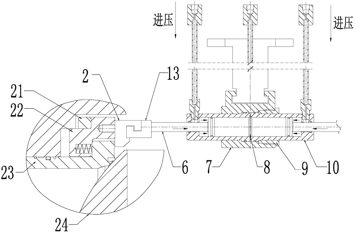
[0021] Such as Figure 1 to Figure 2 The shown installation and disassembly device for a top-loading ball valve includes a hydraulic cylinder, a fixed plate 2 and a limit plate 4. The hydraulic cylinder includes a piston 6 and a cylinder body 10, and two pistons 6 protrude from both ends of the cylinder body 10 respectively. , the fixed plate is arranged at the end of the piston 6, and the outer wall of the middle part of the cylinder body 10 is also sleeved and fixed with a cylinder liner 7, and the side wall of the cylinder lin...


PUM


Abstract

The invention relates to an upper mounting type ball valve mounting and dismantling device which comprises a hydraulic cylinder, a fixed plate and a limiting plate, wherein the hydraulic cylinder comprises two pistons and a cylinder block; the two pistons stretch out of the two ends of the cylinder block separately; the fixed plate is arranged at the end parts of the pistons; a cylinder sleeve isfurther fixed on the outer wall of the middle of the cylinder block in a sleeving manner; a fixture block is further arranged on the side wall of the cylinder sleeve; the limiting plate comprises a plate body and a connecting column integrally formed; one end of the connecting column is fixed with the plate body; the other end of the connecting column is clamped in the fixture block on the side wall of the cylinder sleeve; cylinder block joints are arranged on the side wall of the two ends and in the middle of the cylinder block; and the cylinder block joint in the middle penetrates through the cylinder sleeve. The upper mounting type ball valve mounting and dismantling device is provided with three entrance pressure joints, and pressurization is carried out on the entrance pressure jointsof the dismantling device as demanded, so that the pistons on the two sides do work on a valve seat to mount and dismantle the ball valve and the valve seat; hydraulic action is adopted, the acting force of the pistons is sufficiently large, the acting process of the pistons is smooth and steady, and the upper mounting type ball valve mounting and dismantling device is suitable for mounting and dismantling the large-diameter ball valve and the valve seat subjected to deadlocking due to corrosion of a valve cavity.

Description

technical field [0001] The invention belongs to the technical field of valve installation, in particular to a top-loading ball valve installation and disassembly device. Background technique [0002] Ball valve has become one of the most widely used valves due to its reliable sealing, simple structure and convenient maintenance. Compared with the side-mounted ball valve, the top-entry ball valve has the advantages of fewer leakage points and less influence of pipeline stress on it. At present, the top-entry ball valve is widely used in LNG pipelines, LNG carriers and receiving stations. Therefore, many domestic valve manufacturers All have invested a lot of manpower, material resources and financial resources to study the top entry ball valve. [0003] The top-entry ball valve for pipelines generally has a large diameter. Due to the small space in the inner cavity, the gap between the valve seat and the valve cavity is small and the friction force is large. After a certain ...

Claims


Application Information

Patent Timeline
Patent Type & Authority Applications(China)
IPC IPC(8): B23P19/027F16K5/08
CPCB23P19/027F16K5/08
Inventor 李俊郑应牌周玉庭林仁策赵磊
Owner ZHEJIANG OFILM PETROLEUM EQUIP CO LTD
Why Eureka
Try Eureka