
Spraying sterilization equipment for injection packing bottles

A technology for spray sterilization and bottle packaging, which is applied in the directions of packaging sterilization, packaging, transportation and packaging, can solve the problems of puncturing the bottom of the packaging bottle, affecting the sterilization effect, and not designing a buffer protection structure, and achieves a simple mechanism. , Improve the effect of sterilization and cleaning, and facilitate the effect of plugging and positioning.

Active Publication Date: 2019-02-15
广西河丰药业有限责任公司
View PDF6 Cites 1 Cited by
  • Summary
  • Abstract
  • Description
  • Claims
  • Application Information

AI Technical Summary

Problems solved by technology

[0006] In order to solve the above technical problems, the present invention provides a spray sterilization equipment for injection packaging bottles, to solve the problem that most of the existing spray sterilization equipment adopts the vertical spray washing disinfection method, and the sprayed sterilizing water only It can come into impact contact with the upper part of the Erlenmeyer flask body of the packaging bottle, while the bottle wall of the lower part of the packaging bottle cannot accept direct washing, which will result in incomplete cleaning and disinfection of the packaging bottle, affecting the overall sterilization effect, and the packaging bottle The design and optimization of the positioning support device is not reasonable enough, and there is no special buffer protection structure designed, which will easily cause the bottom surface of the packaging bottle to be punctured during insertion and assembly.

Method used


Image

  • Spraying sterilization equipment for injection packing bottles
  • Spraying sterilization equipment for injection packing bottles
  • Spraying sterilization equipment for injection packing bottles

Examples


Embodiment

[0037] as attached figure 1 to attach Figure 13 Shown:

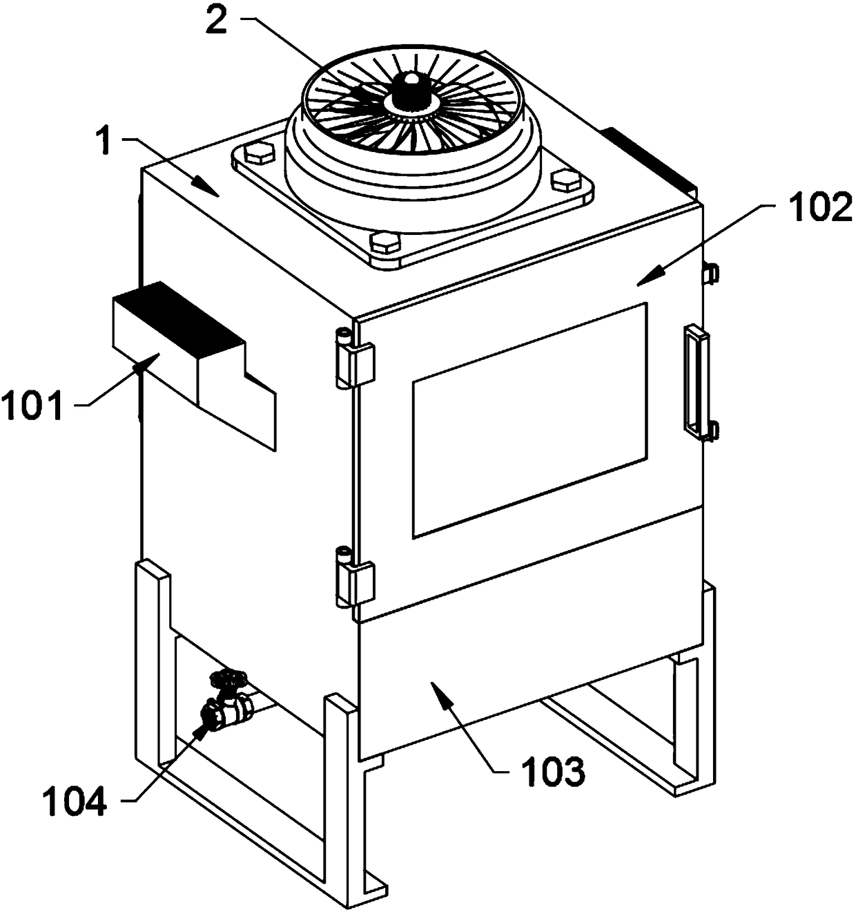
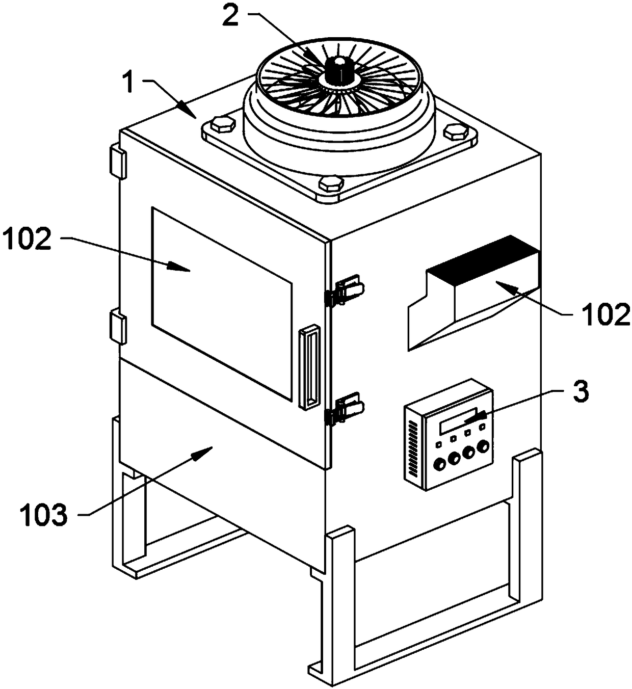
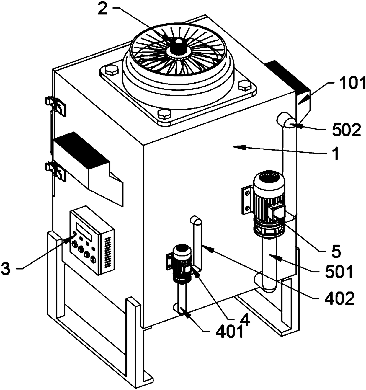
[0038] The present invention provides a spray sterilization equipment for injection packaging bottles, which includes a box body 1, a bent air outlet pipe 101, a box door 102, a water tank 103, a drainage ball valve 104, an electric heater 2, a control box 3, Auxiliary water pump 4, auxiliary water pump suction pipe 401, auxiliary water pump spray pipe 402, main water pump 5, main water pump suction pipe 501, main water pump outlet pipe 502, horizontal water guide pipe 6, nozzle 601, cleaning tank 7, cleaning tank drain pipe 701, solenoid valve 702, track rod 8, packaging bottle bracket 9, sliding groove 10, baffle plate 11, locking bolt 1101, arc-shaped water guide block 1102, packaging bottle 12, packaging bottle insertion rack 13 and ejector rod 131 The box body 1 is arranged in a square shape as a whole, and a baffle plate is welded at the bottom position of the front opening. This baffle plate seals the bottom sp...


PUM


Abstract

The invention provides spraying sterilization equipment for injection packing bottles. The spraying sterilization equipment comprises a box body, a box door, a drainage ball valve, an electric heatingfan and a control electric box, wherein an electromagnetic valve is locked on a central water leakage pipe of a water tank bottom plate in a threaded mode, and a cleaning tank drainage pipe is connected to the tail end of the electromagnetic valve in a threaded mode; a bottom bent section of a water sucking pipe of a main water pump and a bottom bent section of a water sucking pipe of an auxiliary water pump both penetrate through the rear side wall of the box body and are inserted into a water storage trough; two locking bolts are symmetrically arranged at the left and right ends of a bafflein threaded and penetrating modes, and the locking bolts are correspondingly locked in head-end threaded holes of two rail rods; the packing bottles are inserted into packing bottle inserting frames,and the bottom end faces of the packing bottles abut against ejector rods. A circular packing bottle bracket is arranged and can adapt to the rotating feature of sterilization water in a cleaning water tank, rotation of the sterilization water is prevented from being blocked, and rotating speed loss of the sterilization water is reduced.

Description

technical field [0001] The invention belongs to the technical field of spray sterilization equipment, and more specifically relates to a spray sterilization equipment used for injection packaging bottles. Background technique [0002] In the production and filling process of chemical reagents or medical drugs, it is necessary to sterilize and clean glass bottles or other material bottles after filling to ensure that the bottles are clean. Liquid medicines have stricter requirements on the cleaning of the reagent bottle, and the aseptic effect of the bottle can be maintained through high-quality spray cleaning of the reagent bottle. [0003] After searching, for example, the patent No. CN201720635516.2 discloses a cleaning device for injection bottles, including a base, the side wall of the base is connected to a connecting block through a first rotating shaft, and the connecting block is far away from the first rotating shaft One side of the side wall is fixed with an upper...

Claims


Application Information

Patent Timeline
IPC IPC(8): B65B55/02B65D19/44
CPCB65B55/02B65D19/44B65D2519/00815
Inventor 梁林燕叶华锋戴陆颖
Owner 广西河丰药业有限责任公司
Learn More