
Weighbeam type balance beam hoisting tool and method for hoisting steel beam component through same

A technology of balance beams and balance arms, which is applied in the field of hoisting devices for steel beam components, and can solve problems such as difficult coordination, affecting line traffic, and being unable to go on the road alone

Active Publication Date: 2019-02-15
CHINA COMM 2ND NAVIGATIONAL BUREAU 2ND ENG +1
View PDF6 Cites 2 Cited by
  • Summary
  • Abstract
  • Description
  • Claims
  • Application Information

AI Technical Summary

Problems solved by technology

The problem with this method is that, on the one hand, when the components are transferred to the cross-line road, the road must be occupied or temporarily closed, which seriously affects the traffic on the line; secondly, the large-scale lifting equipment cannot be used on the road alone in the urban area, and it needs to be transported to the site by a trailer. , which requires a larger cross-line road and takes a longer time
However, large-scale cranes directly lift components on the cross-line road, which requires high bearing capacity of the road foundation. If the cross-line road is a bridge, it must meet the design load of the bridge, which requires higher road grades, and due to equipment transfer, The assembly and disassembly cycle is long, which has a huge impact on the traffic of cross-line roads, and it is difficult to coordinate and invest a lot

Method used


Image

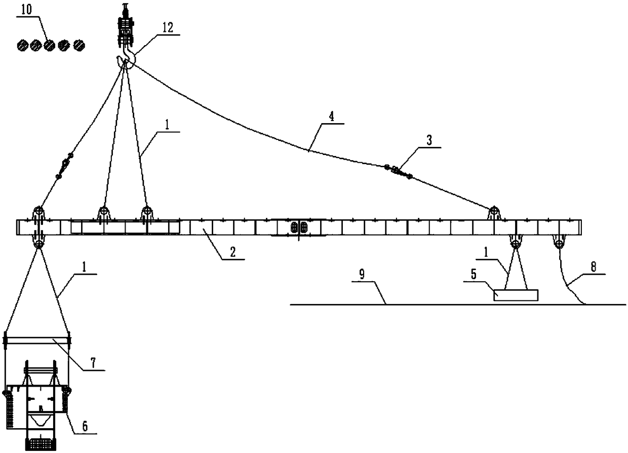
  • Weighbeam type balance beam hoisting tool and method for hoisting steel beam component through same
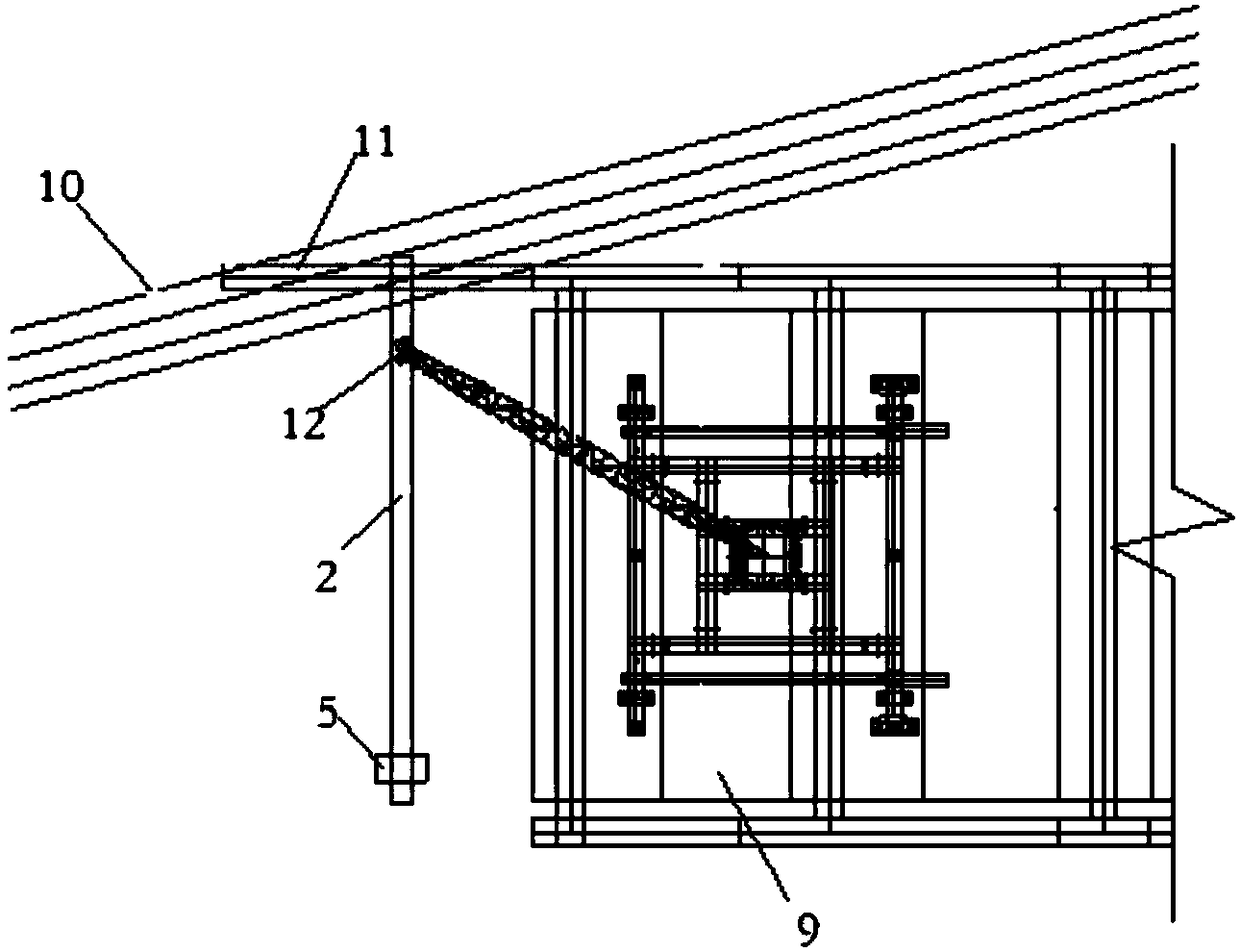
  • Weighbeam type balance beam hoisting tool and method for hoisting steel beam component through same
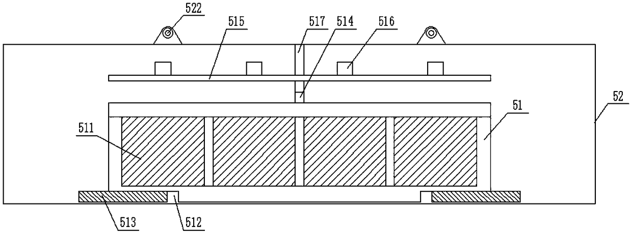
  • Weighbeam type balance beam hoisting tool and method for hoisting steel beam component through same

Examples


Embodiment Construction

[0037] The present invention will be further described in detail below in conjunction with the accompanying drawings, so that those skilled in the art can implement it with reference to the description.

[0038] It should be noted that the experimental methods described in the following embodiments, unless otherwise specified, are conventional methods, and the reagents and materials, if not otherwise specified, can be obtained from commercial sources; in the description of the present invention, The terms "landscape", "portrait", "top", "bottom", "front", "rear", "left", "right", "vertical", "horizontal", "top", "bottom", The orientation or positional relationship indicated by "inner", "outer", etc. is based on the orientation or positional relationship shown in the drawings, which is only for the convenience of describing the present invention and simplifying the description, and does not indicate or imply that the referred device or element must have Certain orientations, co...


PUM


Abstract

The invention discloses a weighbeam type balance beam hoisting tool and a method for hoisting a steel beam component through same. The weighbeam type balance beam hoisting tool comprises a balance beam, a C-beam, a balance weight, a pair of safety steel wire ropes and a cable wind rope, wherein the balance beam is connected through a hoisting steel wire rope; the C-beam is connected to the steel beam component, and the C-beam is connected to one end of the balance beam through the hoisting steel wire rope; the balance weight is connected to the other end of the balance beam through the hoisting steel wire rope; the upper ends of the safety steel wire ropes are connected to a boom hook, and the lower ends of the safety steel wire ropes are correspondingly connected to two ends of the balance beam; the safety steel wire ropes are in a slightly loose state; and one end of the cable wind rope is connected to the other end of the balance beam, and the other end of the cable wind rope is arranged on a bridge. According to the weighbeam type balance beam hoisting tool, the moment balance theory is utilized; the balance is realized through the balance beam based on the length and weight ofthe component and an actuating arm of the balance weight, so that the steel beam component can be mounted, and the component is successfully prevented from being intersected with an upper barrier space, and as a result, the stable hoisting is realized, and as a result, the component hoisting safety is ensured, and the circuit is smooth.

Description

technical field [0001] The invention relates to the field of hoisting devices for steel beam components. More specifically, the present invention relates to a beam-type balance arm spreader and a method for lifting a steel beam member thereof. Background technique [0002] The installation of steel truss girder components for municipal cross-lines (existing roads or track lines) is generally assembled using the symmetrical cantilever of the bridge deck crane, that is, the steel girder components to be installed are hoisted to the normal position of the installation position through the crane's jib and hooks. At the top, the alignment and installation of the steel beam components are carried out by slowly dropping the hook; and because there are obstacles directly above the installation position of the steel beam components, and the distance between the obstacles and the steel beam components to be installed is relatively close, the rotation of the boom will It will cause th...

Claims


Application Information

Patent Timeline
Patent Type & Authority Applications(China)
IPC IPC(8): B66C1/12B66C13/08
CPCB66C1/12B66C13/08
Inventor 刘小勇范波刘颖吴鹏飞张世杰
Owner CHINA COMM 2ND NAVIGATIONAL BUREAU 2ND ENG
Learn More