A glass molding device and its molding process with tin liquid and vacuum pumping
What is AI technical title?
AI technical title is built by Patsnap AI team. It summarizes the technical point description of the patent document.
A vacuuming device and vacuuming technology, applied in glass pressing, glass forming, glass manufacturing equipment, etc., can solve problems such as warping, cracks, and uneven distribution of residual stress in forming components
Inactive Publication Date: 2021-10-29
SHAOYANG UNIV
View PDF8 Cites 0 Cited by
Summary
Abstract
Description
Claims
Application Information
AI Technical Summary
This helps you quickly interpret patents by identifying the three key elements:
Problems solved by technology
Method used
Benefits of technology
Problems solved by technology
However, in the process of using a traditional mold to press molten glass into shape, the force on the glass preform will be uneven, which will easily lead to inconsistent filling rates of each microstructure, and the difference between the surface of the preform and the surface of the mold will make the preform heated or annealed unevenly. , the uneven distribution of residual stress inside the forming element, especially for thin glass plates, is prone to warping and deformation, and even leads to cracks in severe cases
Method used
Image
Click on the blue label to locate the original text in one second.
Reading with bidirectional positioning of images and text.
Examples
Embodiment 1
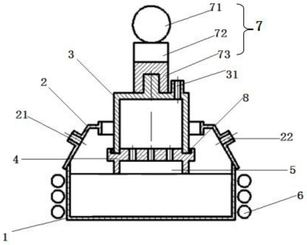
[0044] Refer to attached figure 1 , attached Figure 2a -2d and attached Figure 4 , this embodiment discloses a glass molding device with tin liquid and vacuum pumping, including:
[0045] The liquid tin container 1 is filled with liquid tin.
[0046] Cover 2, cover 2 is arranged on the open end of tin liquid container 1, and encloses molding space with tin liquid container 1; Offers on the cover 2 the nitrogen inlet hole 21 that is used to pass into nitrogen and is used for discharging described Oxygen exhaust holes 22 in the molding space; the center of the cover 2 is provided with a circular through hole for the sleeve 3 to pass through, and the diameter of the circular through hole is not smaller than the maximum diameter of the mold 4 .
[0047] Sleeve 3, one end of the sleeve 3 is closed, one end is open, and its open end is set through the top of the cover 2 towards the liquid surface of the tin liquid, and is slidably connected with the cover 2; the closed end of t...
Embodiment 2
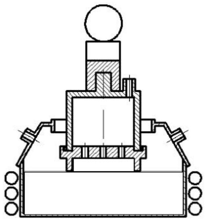
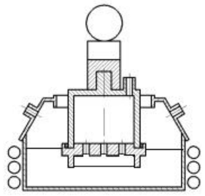
[0063] Refer to attached figure 1 , attached Figure 3a -3d and attached Figure 4 , this embodiment takes the manufacture of micro-columnar glass arrays as an example, the device used is the same as that of embodiment 1, in the specific preparation process, except that the molding process of S3 is different from that of embodiment 1, the rest of the steps are the same as that of embodiment 1.
[0064] Specifically, the specific process of S3 molding in this embodiment is:
[0065] Heat the viscosity of glass 5 to 10 6 ~10 8 After dPa·s, start the sleeve drive device 7, the drive sleeve 3 continues to move towards the bottom wall direction of the tin liquid container 1, until the mold 4 and the glass 5 move below the tin liquid level, start the vacuum device to further reduce The inner pressure of the lower sleeve increases the pressure difference between the sleeve 3 and the molding space. After standing still for 1 min, the glass 5 is filled into the mold 4 to form a mi...
PUM
Abstract
The invention discloses a glass molding device with tin liquid combined with vacuum pumping, which comprises: a tin liquid container, a cover, a sleeve, a vacuum device, a sleeve driving device, a mould, glass and a heating device; the inside of the tin liquid container is filled with Tin liquid, the heating device is used to heat the tin liquid; the cover is set on the open end of the tin liquid container, and forms a molding space with the tin liquid container; the sleeve driving device, the sleeve and the mold are connected in sequence; the glass is in the vacuum device Driven by the drive, it is adsorbed at the bottom of the mold, and the sleeve driving device drives the sleeve to move back and forth toward the bottom wall of the liquid tin container, and drives the glass and the mold to immerse in the liquid tin to complete the molding process, and finally obtain a micro-lens or micro-column glass array. The invention uses tin liquid to heat and soften the glass, and is equipped with a vacuum device to change the pressure inside the sleeve, so that the softened glass is filled into the through hole of the mold, and has the characteristics of high filling efficiency and uniform filling.
Description
technical field [0001] The invention relates to the technical field of molding devices for thin glass elements with microstructures, and more specifically relates to a molding device and molding process for manufacturing microlenses or microcolumnar glass arrays with tin liquid combined with a vacuum device to assist molding. Background technique [0002] The use of compression molding to manufacture optical glass components is an advanced manufacturing technology that can increase productivity and enable mass production to meet market demand. Glass compression molding belongs to thermoforming technology, which is an efficient and high-precision processing method that uses a high-precision mold to compress and deform a glass preform of a certain shape under high temperature and oxygen-free conditions, and directly replicates the mold cavity. The filling rate of the glass preform, the temperature and stress distribution inside the glass directly affect the molding quality of ...
Claims
Application Information
Patent Timeline
Application Date:The date an application was filed.
Publication Date:The date a patent or application was officially published.
First Publication Date:The earliest publication date of a patent with the same application number.
Issue Date:Publication date of the patent grant document.
PCT Entry Date:The Entry date of PCT National Phase.
Estimated Expiry Date:The statutory expiry date of a patent right according to the Patent Law, and it is the longest term of protection that the patent right can achieve without the termination of the patent right due to other reasons(Term extension factor has been taken into account ).
Invalid Date:Actual expiry date is based on effective date or publication date of legal transaction data of invalid patent.

