Gate Drive Sealing Mechanism

A technology of sealing mechanism and gate, which is applied in sea area engineering, construction, barrage/weir, etc. It can solve the problems of poor sealing degree, poor fixing firmness of gate, easy aging of sealing layer and leakage of water, etc.

Active Publication Date: 2020-07-03
NORTH CHINA UNIV OF WATER RESOURCES & ELECTRIC POWER
View PDF3 Cites 0 Cited by
  • Summary
  • Abstract
  • Description
  • Claims
  • Application Information

AI Technical Summary

Problems solved by technology

[0003] Aiming at the problems existing in existing gates such as poor sealing degree, easy aging of the sealing layer and poor fixing firmness of the gate, the present invention provides a gate driving and sealing mechanism

Method used


Image

  • Gate Drive Sealing Mechanism
  • Gate Drive Sealing Mechanism
  • Gate Drive Sealing Mechanism

Examples


Embodiment 1

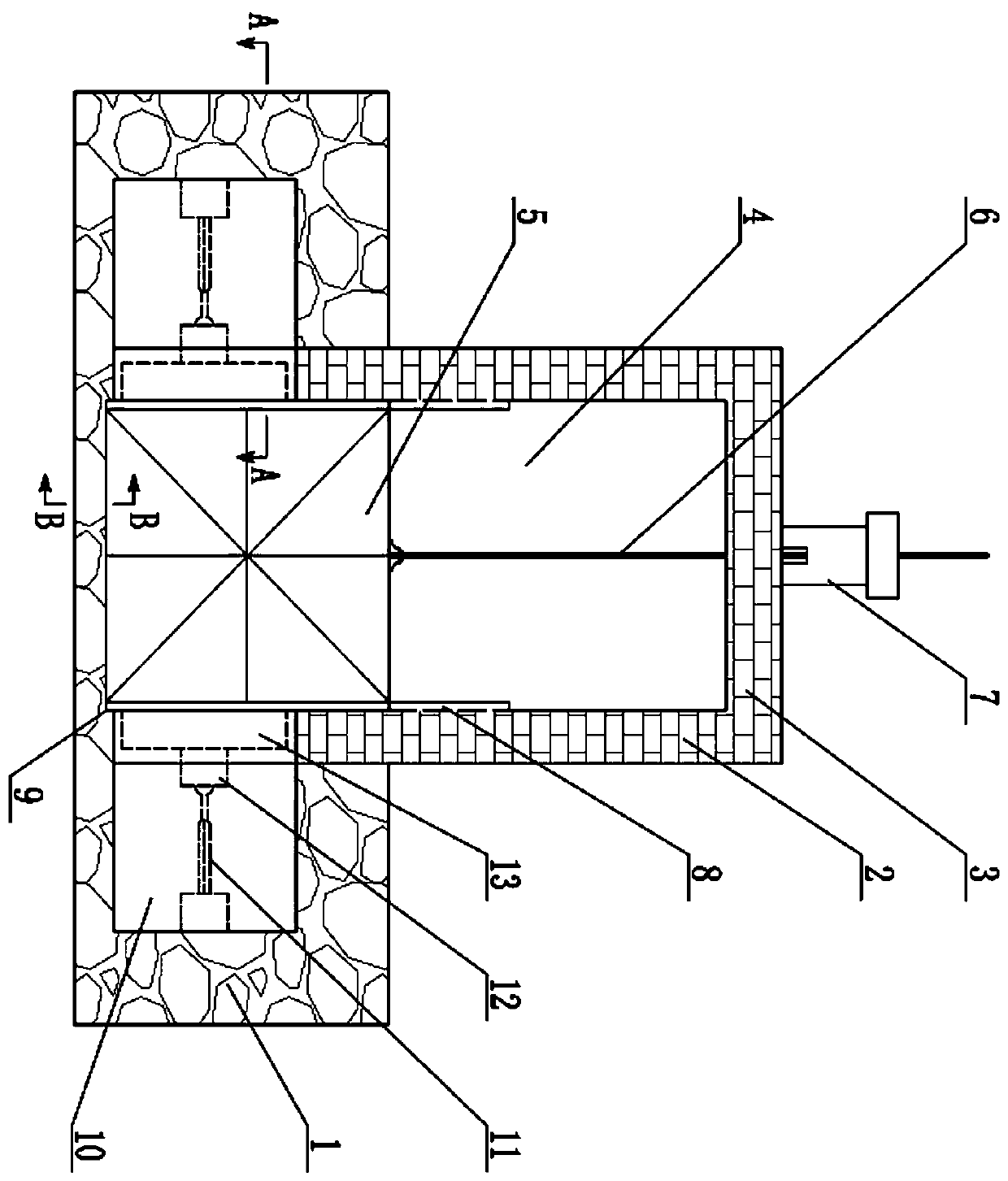
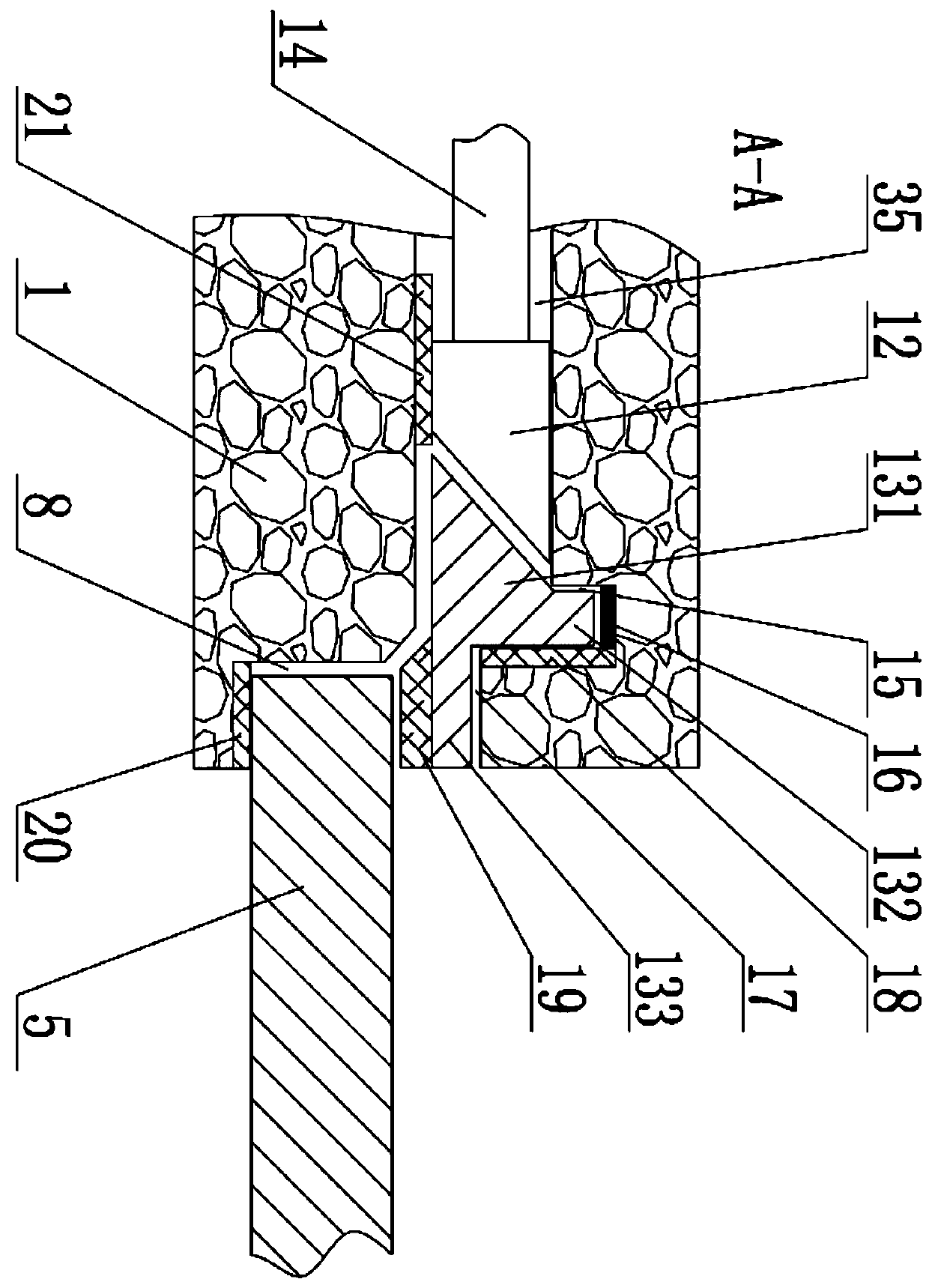
[0018] Embodiment 1: as figure 1 As shown, the foundation 1 is built inward along the side slope of the river, and the middle part of the foundation 1 on both sides forms a water-passing gate. A vertical column 2 is arranged on the upper side of the foundation 1 on both sides and a beam 3 is arranged on the upper end of the column 2 on both sides. , constituting the bracket for the hoisting of the gate 5 and the hoisting section 4, and a hoisting motor 7 is installed in the middle of the upper end of the beam 3.

[0019] The gate 5 is located inside the uprights 2 on both sides, and track grooves 8 are arranged at symmetrical positions on the inner surfaces of the two uprights 2 , and the two sides of the gate 5 are clamped in the track grooves 8 on both sides. A lifting screw 6 is installed in the middle part of the upper end of the gate 5, and the lifting screw 6 is installed in the rotating screw hole at the output end of the lifting motor 7. Here, the lifting motor 7 and ...

Embodiment 2

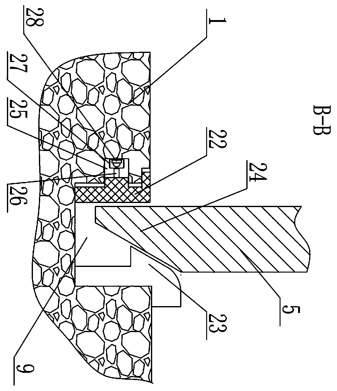
[0025] Embodiment 2: On the basis of Embodiment 1, automatic cooperation with manual control of the hydraulic cylinder 11 and the lifting motor 7 can be realized. Such as Figure 4 As shown, a switch chamber 25 is arranged in the backwater side wall of the bottom tank 9, and a switch seal bag 27 is installed in the switch chamber 25 for sealing the SPDT switch 28, and the SPDT switch 28 is sealed and set in the switch seal bag 27 can be connected with insulated wires without wading.

[0026] The way to drive the SPDT switch 28 is to vertically connect the push rod 26 on the back of the bottom groove extrusion gasket 22, the push rod 26 corresponds to the push knob position of the switch sealing bag 27 and the SPDT switch 28, and the push rod 26 moves Then the SPDT switch 28 switches. The power connection mode of the SPDT switch 28: after the common terminal of the SPDT switch 28 is connected to the coil terminal 1 of the relay, the coil terminal 2 of the relay is connected t...


PUM


Abstract

The invention discloses a gate driving and sealing mechanism. Hydraulic cylinder working chambers are respectively arranged in the foundations on both sides of the gate and hydraulic cylinders are installed horizontally. The front end of the hydraulic cylinder push rod is fixed with a conical push head. The end of the end is provided with a chute and an extruding plate is installed. The rear side of the extruding plate is provided with a tapered push surface, the side is provided with a slide bar, and the front side is provided with a translational pressure plate. The slide bar is located in the chute and is in line with There is a matching gap at the bottom of the chute; the conical push head connected to the hydraulic cylinder push rod matches and docks with the conical push surface on the rear side of the extrusion plate body. The invention has the function of clamping and fixing both sides of the gate, and at the same time of clamping and fixing, it also provides the gate with high-pressure sealing conditions, so as to achieve the functions of strengthening fixation and water-stopping on both sides of the gate. During the opening process, no pressure is generated on the rubber cushion of the sealing part, so as to ensure that the service life of the rubber cushion will not be affected by the increase of pressure.

Description

technical field [0001] The invention belongs to the technical field of water conservancy project gate sealing, and in particular relates to a controllably driven gate sealing mechanism. Background technique [0002] Gates are an important part of hydraulic structures, which can be used to intercept water flow, control water level, regulate flow, discharge sediment and floating objects, etc. At present, there is a phenomenon of flow leakage in the existing gate seals, and the upstream water pressure will leak from the periphery of the gate during long-term use. The sealing compression of traditional small and medium-sized soft-sealed gates is fixed. If there is an error in manufacturing, the compression will be too small and the gate will leak seriously; or the opening and closing force of the gate will be too large due to the compression. Moreover, although a water-tight sealing layer is used in the sealing process between the existing gate and the track groove, the sealing...

Claims


Application Information

Patent Timeline
Patent Type & Authority Patents(China)
IPC IPC(8): E02B7/28E02B7/36E02B7/54
CPCE02B7/28E02B7/36E02B7/54
Inventor 张宏洋王晓辉郑志杰班汉林丁泽霖张先起
Owner NORTH CHINA UNIV OF WATER RESOURCES & ELECTRIC POWER
Why Eureka
Try Eureka