
Finished drainage gutter drainage system

A drainage system and drainage ditch technology, applied in waterway systems, sewer pipeline systems, drainage structures, etc., can solve the problems of difficult slope adjustment, frequent maintenance, and inability to replace, and achieve the effect of reducing impact and pipeline safety.

Active Publication Date: 2019-02-15
安徽海米新材料有限公司
View PDF6 Cites 5 Cited by
  • Summary
  • Abstract
  • Description
  • Claims
  • Application Information

AI Technical Summary

Problems solved by technology

[0002] Existing underground network pipe inspection wells for municipal engineering are mostly brick concrete inspection wells, which mainly have the following disadvantages: firstly, the strength is low, and the support strength of the brick structure is low, especially the part of the brick structure near the road surface due to the variable diameter and shrinkage. It is easy to collapse due to the impact of force; secondly, the construction period of the well body is long and the construction is complicated. Due to the manual on-site stacking, the requirements for civil engineering are high, and the degree of standardization, generalization, and serialization is poor. The amount of manual work and materials used is an important factor affecting the quality; In addition, there are defects such as non-replacement, easy rupture and leakage, which cause pollution, etc., and frequent maintenance is required. Moreover, it is troublesome to retrieve mud or other sundries in the traditional inspection well, which is mainly operated by sanitation workers with special workpieces. , causing inconvenience to the work of sanitation workers
[0005] However, when the urban drainage ditches are densely covered, the slope of the drainage ditches needs to be adjusted due to the different slopes of each point in the city. However, the existing drainage ditches are difficult to adjust the slope due to the direct connection between the two ends. Moreover, the drainage volume of each point in the city is different, and it is difficult to splice the multi-diameter of the drainage ditch

Method used


Image

  • Finished drainage gutter drainage system
  • Finished drainage gutter drainage system
  • Finished drainage gutter drainage system

Examples


Embodiment Construction

[0030] The following will clearly and completely describe the technical solutions in the embodiments of the present invention with reference to the accompanying drawings in the embodiments of the present invention. Obviously, the described embodiments are only some, not all, embodiments of the present invention. Based on the embodiments of the present invention, all other embodiments obtained by persons of ordinary skill in the art without making creative efforts belong to the protection scope of the present invention.

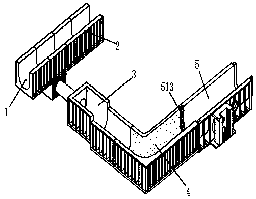
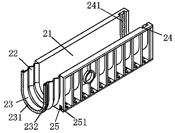
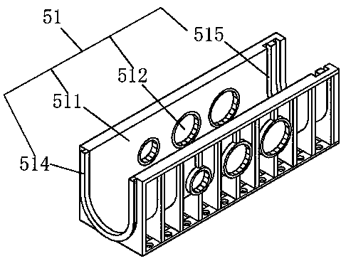
[0031] Examples, see Figure 1-7 , a finished gutter drainage system, comprising a drainage pipe 1 connected to a municipal pipe, the drainage pipe 1 comprising a multi-section piping unit 2, a trapezoidal piping unit 3, a corner piping unit 4 and a split piping unit 5, and the multi-section piping unit The pipeline unit 2, the trapezoidal pipeline unit 3, the corner pipeline unit 4 and the split pipeline unit 5 are detachably connected;

[0032] The multi-se...


PUM


Abstract

The invention provides a finished drainage gutter drainage system, which comprises a drainage pipe connected with a municipal pipe. The drainage pipe comprises a multi-section pipe unit, a trapezoidalpipe unit, a corner pipe unit and a split pipe unit. The multi-section pipe unit, the trapezoidal pipe unit, the corner pipe unit and the split pipe unit are connected detachably and separately. Thefinished drainage gutter drainage system can save more materials by assembling an arc route through the multi-section pipe unit, while reducing the path distance. The trapezoidal pipe unit is used forlaying the slope unit to strengthen the support of the slope unit gutter. The split pipe unit is used for increasing the water drainage. The corner pipe unit is assembled at a large angle, which makes the whole drainage system drain faster and safer while saving material and reducing cost.

Description

technical field [0001] The invention relates to the technical field of urban drainage pipe networks, in particular to a finished drainage ditch drainage system. Background technique [0002] Existing underground network pipe inspection wells for municipal engineering are mostly brick concrete inspection wells, which mainly have the following disadvantages: firstly, the strength is low, and the support strength of the brick structure is low, especially the part of the brick structure near the road surface due to the variable diameter and shrinkage. It is easy to collapse due to the impact of force; secondly, the construction period of the well body is long and the construction is complicated. Due to the manual on-site stacking, the requirements for civil engineering are high, and the degree of standardization, generalization, and serialization is poor. The amount of manual work and materials used is an important factor affecting the quality; In addition, there are defects suc...

Claims


Application Information

Patent Timeline
IPC IPC(8): E03F5/04E03F3/02E03F3/04
CPCE03F3/02E03F3/04E03F5/04E03F5/041Y02A30/60
Inventor 马克尧
Owner 安徽海米新材料有限公司
Learn More