
Method for realizing active optical system of large field survey telescope

A technology of optical system and implementation method, applied in the field of optical system, achieves the effect of fast speed, simple implementation method and high precision

Active Publication Date: 2019-02-15
ZIJINSHAN ASTRONOMICAL OBSERVATORY CHINESE ACAD OF SCI
View PDF3 Cites 6 Cited by
  • Summary
  • Abstract
  • Description
  • Claims
  • Application Information

AI Technical Summary

Problems solved by technology

With the birth of new concepts in the 1980s, in order to enhance the light-gathering ability of the telescope, the diameter of the primary mirror should be more than 4 meters. Obviously, the above-mentioned traditional methods of maintaining image quality and preventing lens deformation due to gravity Limitations by price and structural weight no longer apply

Method used


Image

  • Method for realizing active optical system of large field survey telescope

Examples


Embodiment Construction

[0032] The following description and drawings illustrate specific embodiments of the invention sufficiently to enable those skilled in the art to practice them. Other embodiments may incorporate structural, logical, electrical, process, and other changes. The examples merely represent possible variations. Individual components and functions are optional unless explicitly required, and the order of operations may vary. Portions and features of some embodiments may be included in or substituted for those of other embodiments. The scope of embodiments of the present invention includes the full scope of the claims, and all available equivalents of the claims.

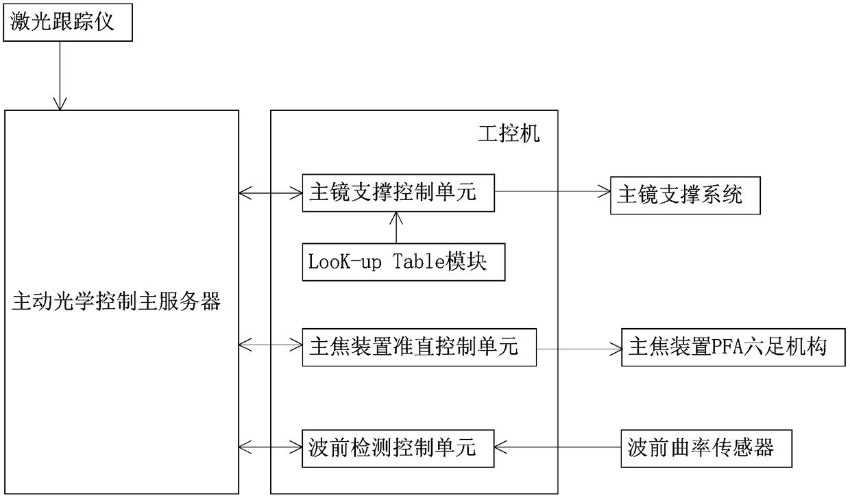
[0033] In some illustrative embodiments, some terms are explained in this article: the active optical system is a wavefront correction technology adopted to eliminate the deformation of the telescope's optical system and bracket due to factors such as gravity and temperature.

[0034] Zernike polynomials consist of an in...


PUM


Abstract

The invention provides a method for realizing an active optical system of a field survey telescope. The method comprises steps that: an active optical control main server sends a gravitational deformation correction instruction to an industrial computer; the active optical control main server sends an instruction for measuring a collimation error of a main focus device to the industrial computer;the active optical control main server sends an instruction for performing a preliminary correction on the collimation error of the main focus device to a collimation control unit of the main focus device of the industrial computer, thereby performing active optical correction on a field survey telescope. The method is simple and efficient. After corrected by the active optical system, the axial positioning error is expected to reach 0.002 mm, the eccentric error is expected to be within 0.02 mm, and the tilt error is expected to be within 0.001 degrees after the main focus device is corrected. Without considering the influence of seeing, the wavefront error RMS is within 0.05, the overall image quality mean is controlled below 5 microns, and the image quality degradation is controlled within 5% after correcting the gravitational deformation and thermal deformation of a main mirror by the active optical system.

Description

technical field [0001] The invention belongs to the technical field of optical systems, and in particular relates to a method for realizing an active optical system of a large-field survey telescope. Background technique [0002] An automated survey telescope is a type of telescope. It is suitable for observing extended celestial bodies and performing sky survey observations. With the birth of new concepts in the 1980s, in order to enhance the light-gathering ability of the telescope, the diameter of the primary mirror should be more than 4 meters. Obviously, the above-mentioned traditional methods of maintaining image quality and preventing lens deformation due to gravity Restrictions by price and structural weight no longer apply. In order to improve the image quality of large and medium-sized telescopes, the built-in optical correction components automatically adjust the image quality during the observation process, and these correction components work at relatively low...

Claims


Application Information

Patent Timeline
IPC IPC(8): G02B26/06G02B27/00
CPCG02B26/06G02B27/0025
Inventor 王海仁梁明姚大志左营喜郑宪忠
Owner ZIJINSHAN ASTRONOMICAL OBSERVATORY CHINESE ACAD OF SCI
Learn More