Drawing method of an indoor plan

A technology of floor plan and square difference, which is applied in the field of indoor floor plan drawing, can solve problems such as inaccurate size, heavy drawing workload, and difficult measurement, and achieve the effect of accurate size, reduced workload, and fast drawing speed

Pending Publication Date: 2019-02-15
常州畅信网络技术有限公司
View PDF5 Cites 1 Cited by
  • Summary
  • Abstract
  • Description
  • Claims
  • Application Information

AI Technical Summary

Problems solved by technology

[0003] The technical problem to be solved by the present invention is: in order to solve the problems of difficult measurement, inaccurate size, and large drawing workload in drawing indoor floor plans in the prior art, the present invention provides a method for drawing indoor floor plans to solve the above problems

Method used


Image

  • Drawing method of an indoor plan
  • Drawing method of an indoor plan
  • Drawing method of an indoor plan

Examples


Embodiment 2

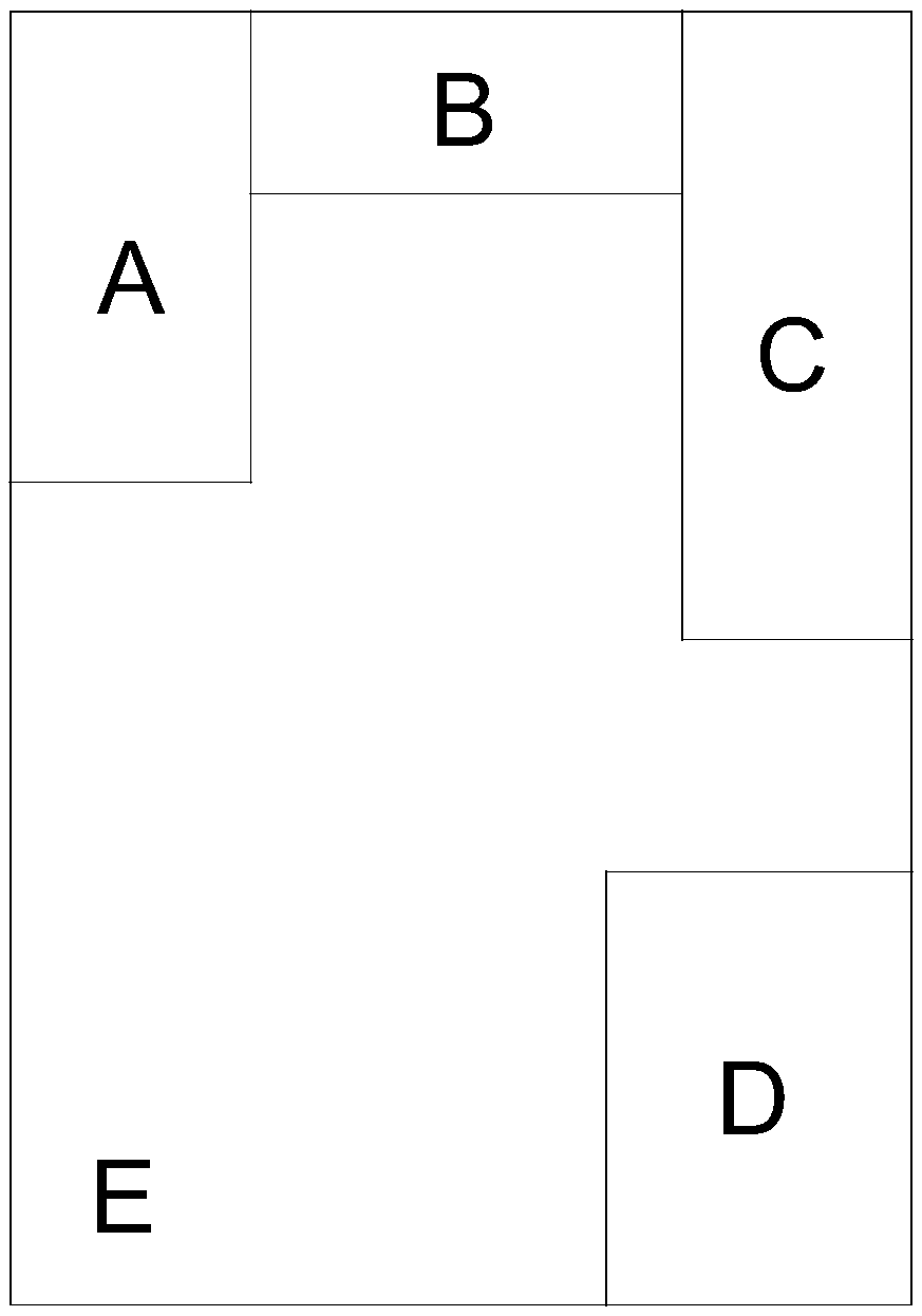
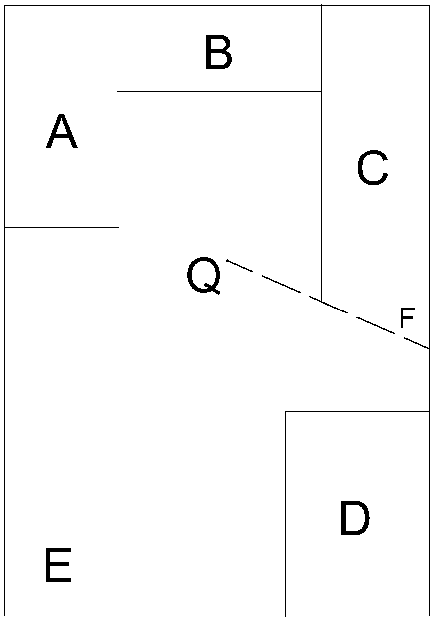
[0046] In the above example, the first extreme point and the reference point are set to be the same point because the discrete points constituting the boundary of the indoor floor plan can be completely obtained through one scan. Such as Image 6 What is shown is another indoor plan view. From the figure, since the upper end of area D is above the lower end of area C, it is impossible to scan all the boundaries at one time, and at least two scans are required, as shown in Figure 5 Shown is a kind of embodiment 2 of the drawing method of indoor floor plan, comprises the following steps:

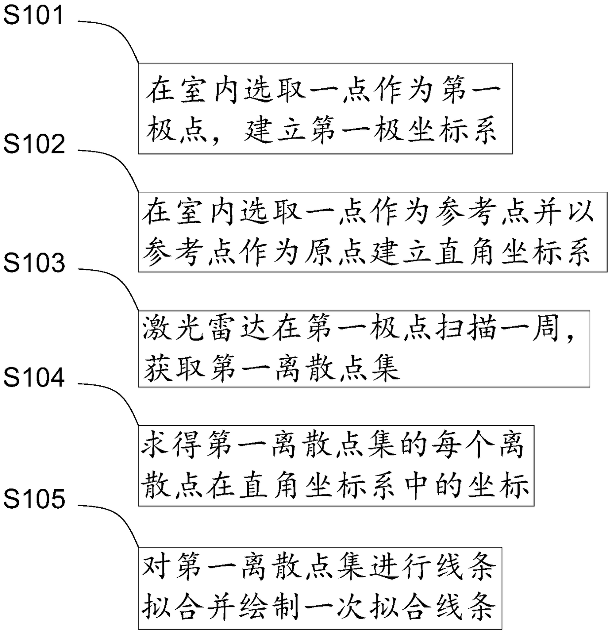
[0047] S201. Select a point indoors as the first pole, and establish a first polar coordinate system;

[0048] S202. Select a point indoors as a reference point and establish a rectangular coordinate system with the reference point as the origin. The first polar coordinate system and the rectangular coordinate system are in the same horizontal plane; a benchmark is set on the reference point...


PUM


Abstract

The invention provides a drawing method of an indoor plan diagram, comprising the following steps: S1, a point is selected as a first pole in the indoor, and a first pole coordinate system is established; 2, selecte a point in that room as a reference point and taking the reference point as an origin to establish a rectangular coordinate system, wherein the first polar coordinate system and the rectangular coordinate system are in the same horizontal plane; This method of drawing interior plans does not require a person to measure the dimensions of every part of the room, Also does not need the designer to draw the indoor floor plan according to the measured size, only needs to select the suitable position to collect the coordinate data of the indoor outline, will automatically draw the indoor floor plan, the size is accurate, the drawing speed is fast, reduced the workload of drawing the floor plan.

Description

technical field [0001] The invention relates to the technical field of indoor structure surveying and mapping, in particular to a method for drawing an indoor plan. Background technique [0002] Before decoration, professional interior designers are usually invited to design according to the area, structure and layout of the interior. Before the design, it is necessary to survey and map the interior and draw the initial interior floor plan according to the results of the survey and mapping. The most primitive way of indoor surveying and mapping is to use a tape measure to measure the size of each part of the room one by one. This method is inefficient and has large measurement errors. In recent years, with the popularization of laser range finders, tape measures have been gradually replaced by them. Laser range finders have the advantages of fast measurement, single-person operation, convenient measurement, and accuracy. However, it is still necessary to measure every part o...

Claims


Application Information

Patent Timeline
Patent Type & Authority Applications(China)
IPC IPC(8): G06F17/50
CPCG06F30/13
Inventor 贺云鹏倪铭
Owner 常州畅信网络技术有限公司
Why Eureka
Try Eureka