Cable bracket device used in ship construction and mounting and use method thereof

A cable bracket and cable installation technology, which is applied in the direction of electrical components, etc., can solve the problems that the length and height cannot be fully adapted to meet the needs, prolong the ship construction dock cycle, and cannot guarantee the cable bending radius, etc., so as to reduce the amount of subsequent operations , Good application value, simple structure effect

Inactive Publication Date: 2019-02-15
SHANGHAI JIANGNAN CHANGXING SHIPBUILDING
View PDF6 Cites 1 Cited by
  • Summary
  • Abstract
  • Description
  • Claims
  • Application Information

AI Technical Summary

Problems solved by technology

[0002] A large amount of cable laying work is involved in the ship construction process, and the cable tray is the main cable laying support and channel. Although the cable tray is used as a standard part in electrical outfitting, its length and height cannot fully adapt match the actual needs
[0003] At present, in the conventional construction process of the shipyard, due to the manufacturing error of the hull section, the welding construction error of the bracket, and the actual manufacturing error of the material, etc., there are often large gaps between the cable bracket and the penetration piece, the cable bracket and the equipment stuffing box. Drop or distance, a large height difference often cannot guarantee the bending radius of the cable, and a large distance cannot guarantee the cable binding standard. When adjusting and reworking, the construction difficulty increases
To a certain extent, it prolongs the construction period of the ship and reduces the efficiency of shipbuilding

Method used


Image

  • Cable bracket device used in ship construction and mounting and use method thereof
  • Cable bracket device used in ship construction and mounting and use method thereof
  • Cable bracket device used in ship construction and mounting and use method thereof

Examples


Embodiment Construction

[0023] The backing plate device used between the cable bracket and the cable in ship construction will be further elaborated below in conjunction with the accompanying drawings and specific examples, in order to understand the structure type and use of the backing plate device more clearly way, but it should not be used to limit the present invention to ships

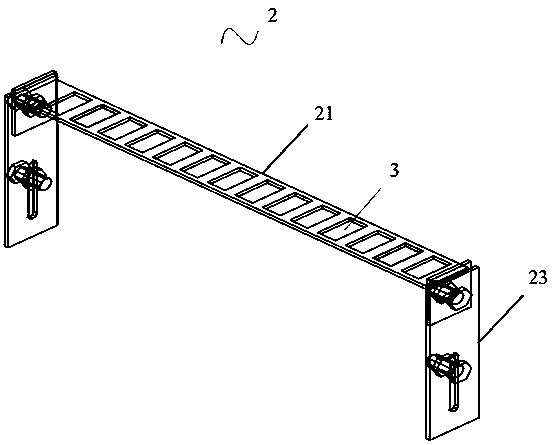
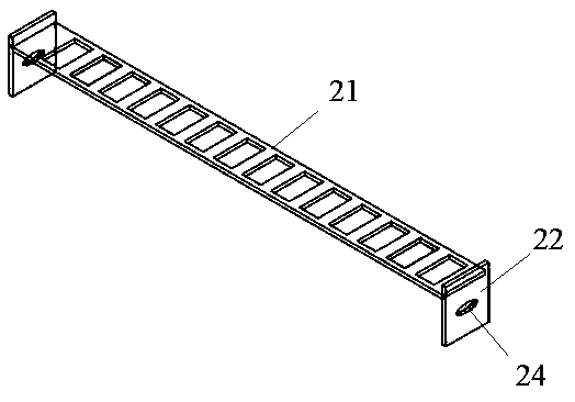
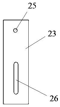
[0024] Such as Figure 1-Figure 6 As shown, this embodiment is used for the cable bracket device in shipbuilding, and the device includes a cable bracket 1, and the cable bracket 1 includes a cable installation plate 11, a bracket outer guide plate 12 and a support leg 13, and the cable installation The two ends of the plate 11 are respectively connected with the bracket outer guide plate 12, the supporting legs 13 are installed on the end of the bracket outer guide plate 12, and one end of the cable bracket 1 is provided with a cable backing plate 2, and the cable backing plate 2 Including a panel 21, a side plate 22 ...


PUM


Abstract

The invention discloses a cable bracket device used in ship construction. The cable bracket device comprises a cable bracket, wherein the cable bracket comprises a cable mounting plate, a bracket outer side guide plate and supporting legs, wherein the two ends of the cable mounting plate are connected with the bracket outer side guide plate separately; the supporting legs are arranged at the end of the bracket outer side guide plate; a cable base plate is arranged at one end of the cable bracket; the cable base plate comprises a panel, side plates and a connecting plate, wherein the side plates are fixedly arranged at the two ends of the panel, and a first bolt hole is formed in each side plate; a second bolt hole is formed in one end of the connecting plate, and a waist-shaped hole is formed in the other end of the connecting plate; the side plates are in bolt connection with the connecting plate at the corresponding ends respectively; and the connecting plate is movably connected with the bracket outer side guide plate through the waist-shaped holes. By virtue of the cable base plate, the height difference and spacing between the bracket and a run-through part and between the bracket and an equipment stuffing box can be flexibly adjusted, so that the bending radius of the cable can be ensured, and damage to the cable can be prevented.

Description

technical field [0001] The invention relates to the field of shipbuilding, in particular to a cable bracket device used in shipbuilding and a method for installing and using the same. Background technique [0002] A large amount of cable laying work is involved in the ship construction process, and the cable tray is the main cable laying support and channel. Although the cable tray is used as a standard part in electrical outfitting, its length and height cannot fully adapt Match the actual needs. [0003] At present, in the conventional construction process of the shipyard, due to the manufacturing error of the hull section, the welding construction error of the bracket, and the actual manufacturing error of the material, etc., there are often large gaps between the cable bracket and the penetration piece, the cable bracket and the equipment stuffing box. Drop or spacing, a large height difference often cannot guarantee the bending radius of the cable, and a large spacing ...

Claims


Application Information

Patent Timeline
Patent Type & Authority Applications(China)
IPC IPC(8): H02G3/04
CPCH02G3/0406
Inventor 杨雯许帆周均怡周翠兰秦涛
Owner SHANGHAI JIANGNAN CHANGXING SHIPBUILDING
Why Eureka
Try Eureka