Overheat detection protection circuit for power device

A technology for detecting protection and power devices, applied in emergency protection circuit devices, circuit devices, emergency protection devices with automatic disconnection, etc., can solve the problems of increasing costs, many circuits, occupying CPU resources, etc., to achieve cost savings and flexible circuits. The effect of changing and reducing the development cycle

Pending Publication Date: 2019-02-15
武汉精能电子技术有限公司
View PDF20 Cites 0 Cited by
  • Summary
  • Abstract
  • Description
  • Claims
  • Application Information

AI Technical Summary

Problems solved by technology

Although this method can achieve better results, it uses more circuits, and there are problems such as sampling circuit power supply, isolation, occupying CPU resources, and increasing costs.

Method used


Image

  • Overheat detection protection circuit for power device
  • Overheat detection protection circuit for power device
  • Overheat detection protection circuit for power device

Examples


Embodiment Construction

[0016] The present invention will be further described in detail below in conjunction with the accompanying drawings and specific embodiments to facilitate a clear understanding of the present invention, but they do not limit the present invention.

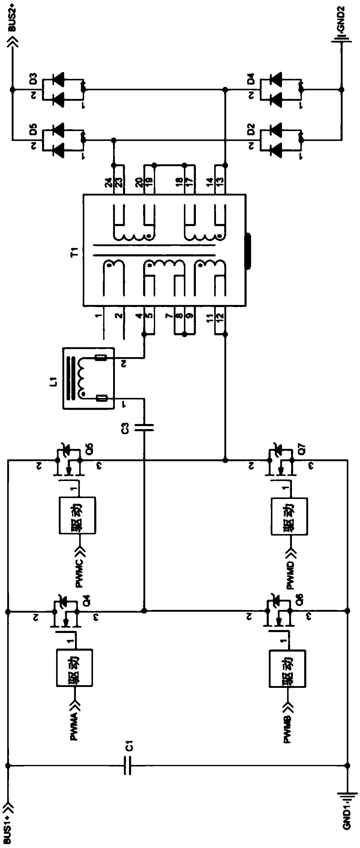
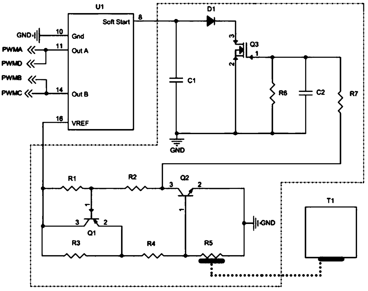
[0017] Such as figure 1 , figure 2 As shown, a power device overheat detection and protection circuit of the present invention includes a resistor R2, a resistor R4, a resistor R6, a triode Q2, a MOS transistor Q3 and a temperature sensor R5 for detecting the temperature of the power device, and the resistor R2 is connected in series with the resistor R6 , the other end of the resistor R2 is used to connect the reference voltage output end of the PWM control chip, and the other end of the resistor R6 is grounded; the resistor R4 is connected in series with the temperature sensor R5, and the other end of the resistor R4 is used to connect the reference voltage output end of the PWM control chip, so The other end of the temperatur...


PUM


Abstract

The invention discloses an overheat detection protection circuit for a power device. The overheat detection protection circuit comprises a resistor R2, a resistor R4, a resistor R6, a triode Q2, an MOS transistor Q3 and a temperature sensor R5, wherein the resistor R2 is connected in series with the resistor R6; the other end of the resistor R2 is used for connecting a reference voltage output endof a PWM (Pulse Width Modulation) control chip; the other end of the resistor R6 is grounded; the resistor R4 is connected in series with the temperature sensor R5; the other end of the resistor R4 is used for connecting the reference voltage output end of the PWM control chip; the other end of the temperature sensor R5 is grounded; a temperature contact of the temperature sensor R5 is in contactwith the power device; a base electrode of a triode Q2 is connected between the resistor R4 and the temperature sensor R5; an emitting electrode of the triode Q2 is grounded; a collecting electrode of the triode Q2 is connected between the resistor R2 and the resistor R6; a grid electrode of the MOS transistor Q3 is connected between the resistor R2 and the resistor R6; a source electrode of theMOS transistor is grounded; and a drain electrode of the MOS transistor is used for connecting a soft start control end of the PWM control chip. The simple protection circuit is designed by flexible use of the pin characteristic of the PWM control chip, and has the advantages of simple structure, low cost and high portability.

Description

technical field [0001] The invention belongs to the technical field of circuit protection, and in particular relates to a power device overheat detection and protection circuit. Background technique [0002] With the development of modern computer and automation technology, as a functional device for the perception, collection, conversion, transmission and processing of various information, the role of temperature sensors has become increasingly prominent, and has become an indispensable part of automatic detection, automatic control systems and measurement tests. Technical tools are used in various fields of industrial R&D, production and daily life. For example, the power density of devices in the standard instrument industry continues to increase, and the devices operate under high-power conditions. How to ensure that the power transformers and switching devices in the instruments will not cause system collapse due to overheating is particularly important. [0003] At pr...

Claims


Application Information

Patent Timeline
Patent Type & Authority Applications(China)
IPC IPC(8): H02H5/04
CPCH02H5/047
Inventor 张小磊
Owner 武汉精能电子技术有限公司
Why Eureka
Try Eureka